Lanier RC 84" Stinger


 02-07-2024, 04:04 PM
#77

Thread Starter
Join Date: Jun 2008
Location: Perth WA, AUSTRALIA
Posts: 1,208
Likes: 0
Received 12 Likes
on
12 Posts
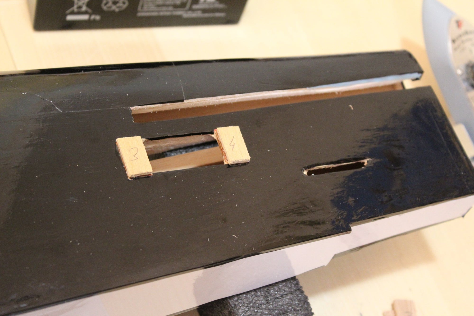
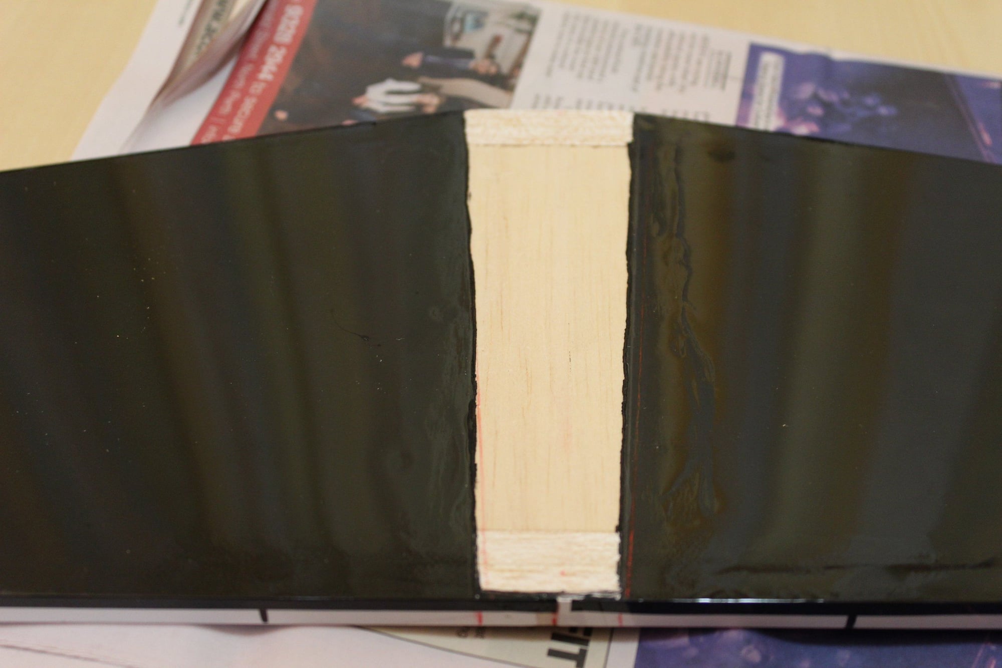
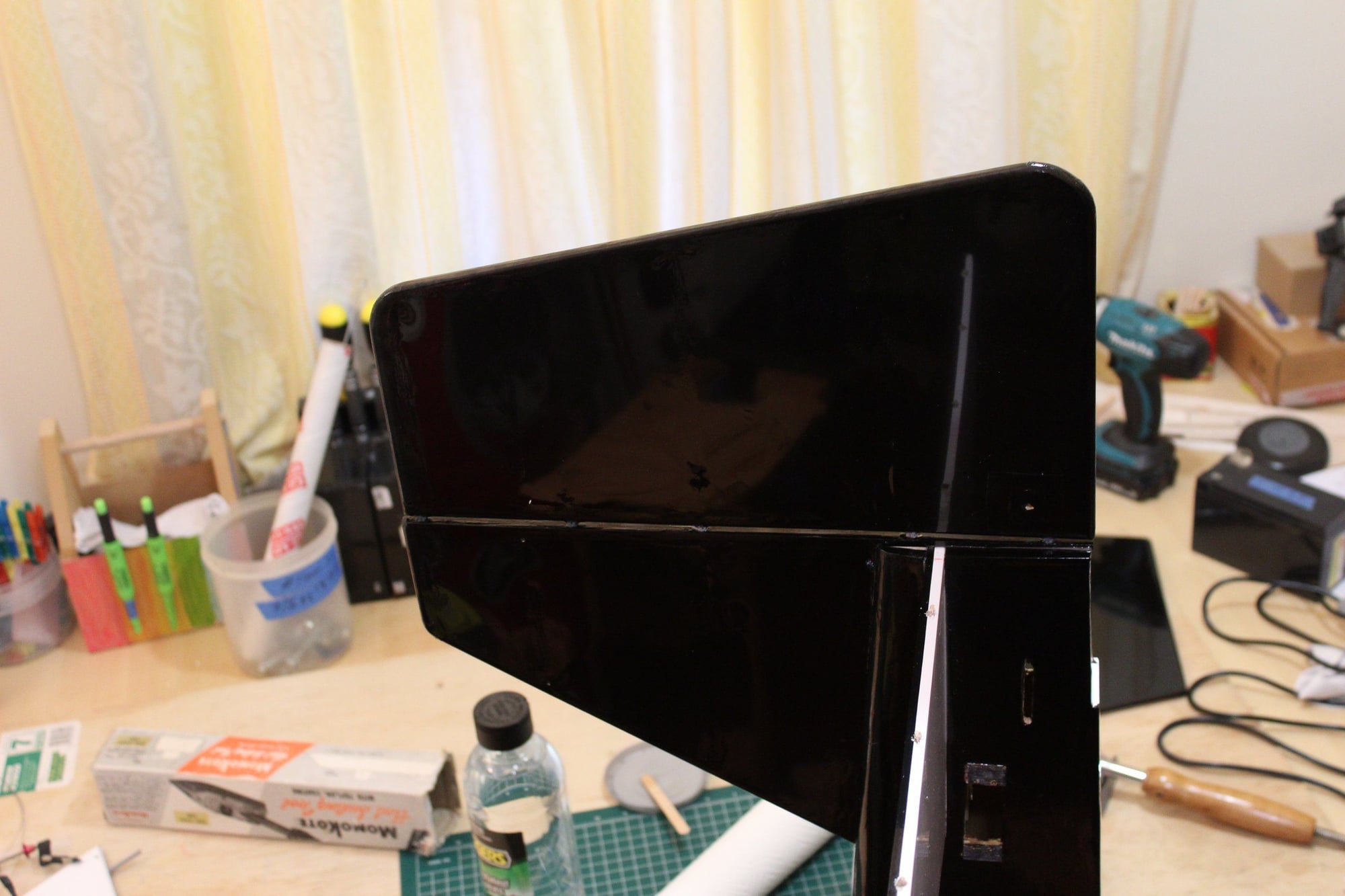
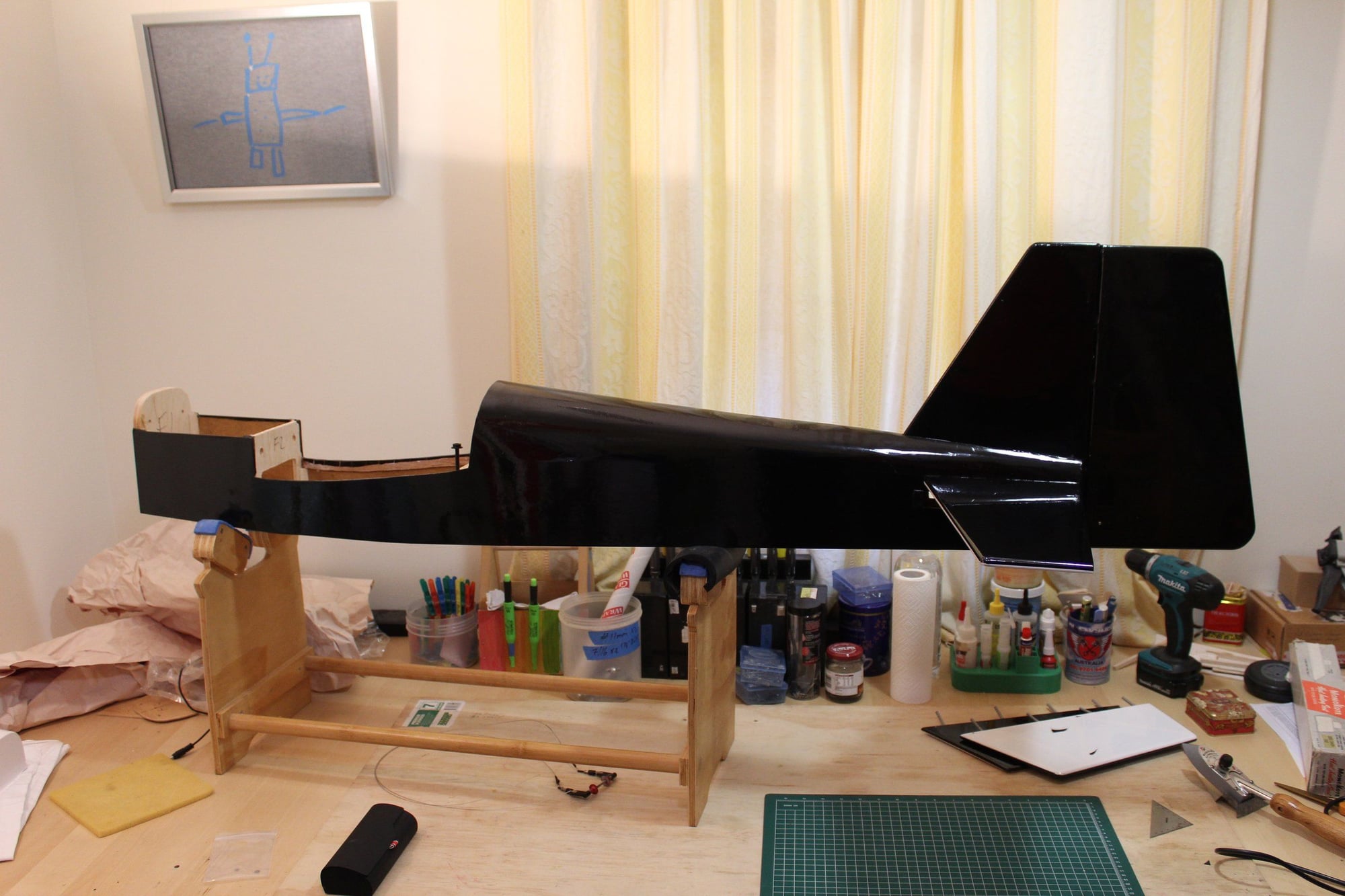
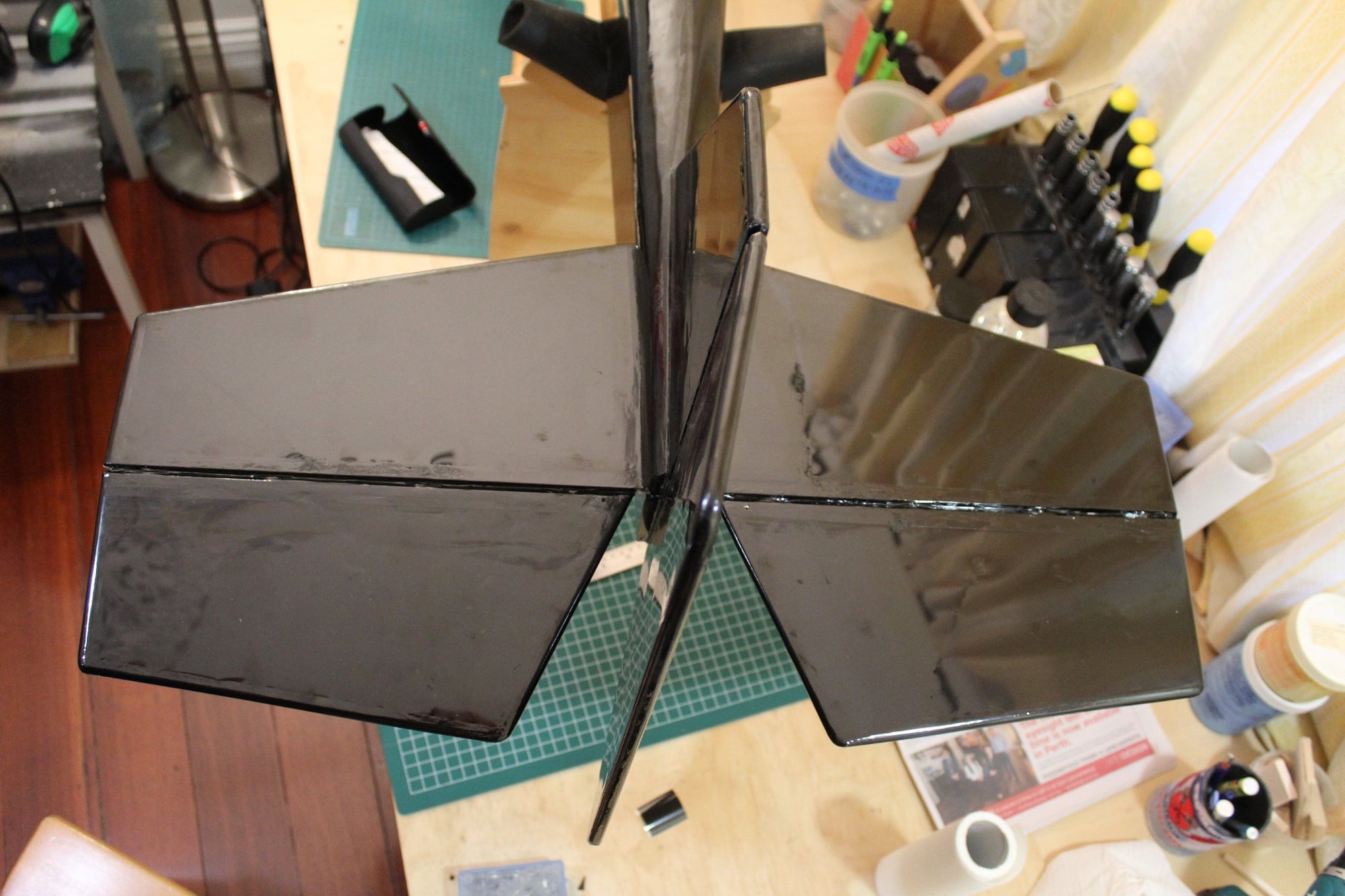
I removed the covering next to the elevators servo mounting position and glued plywood doublers (for the servo screws to bite into).
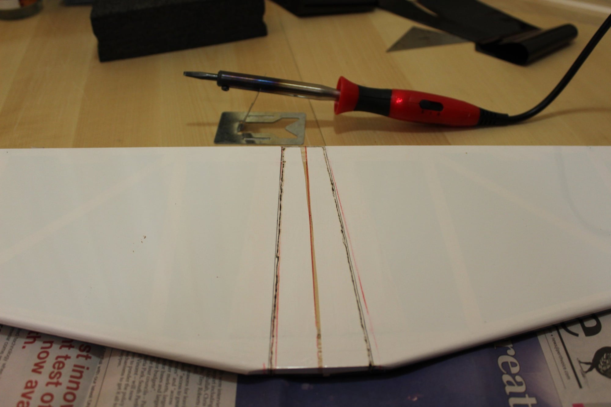
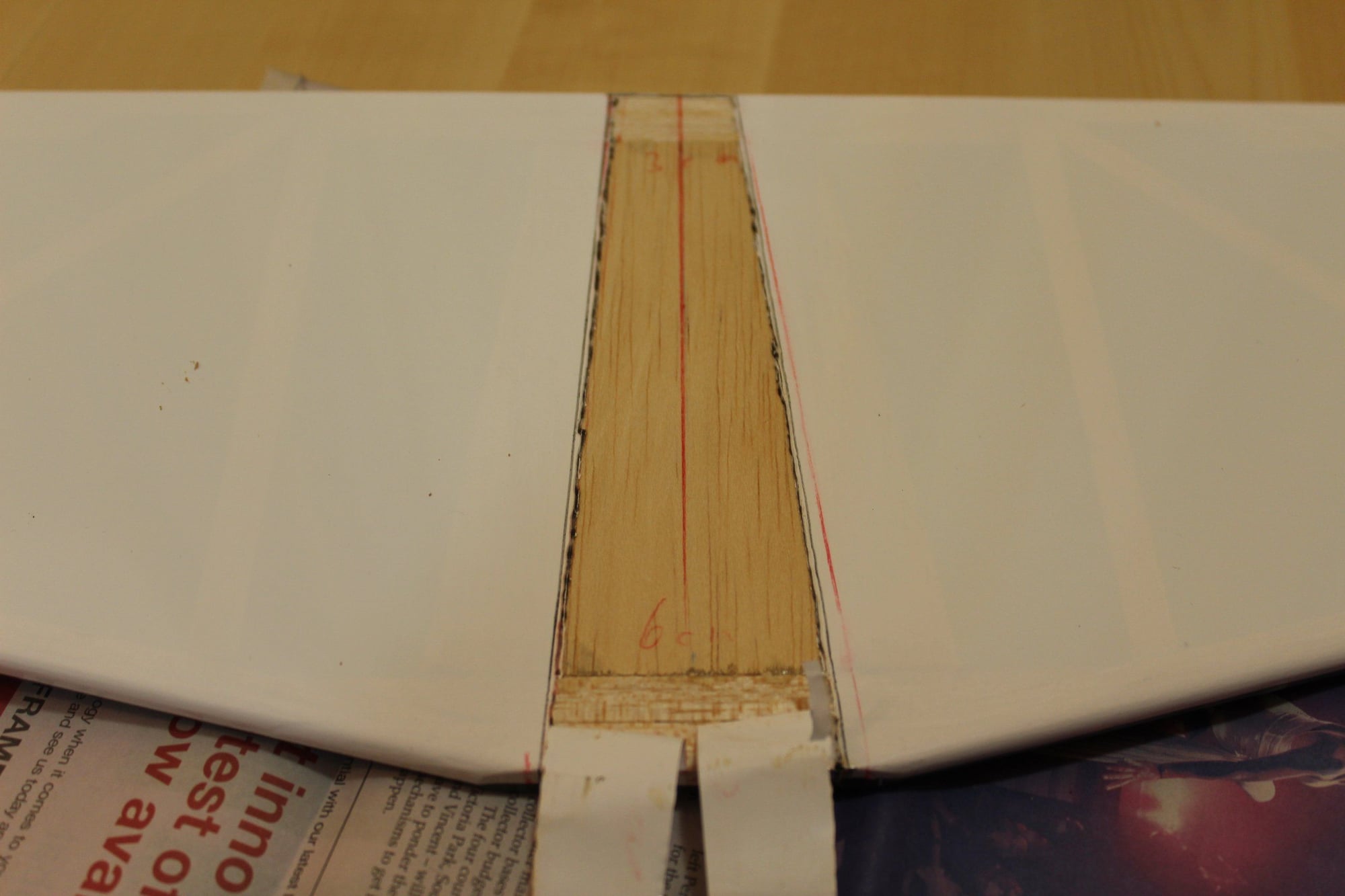
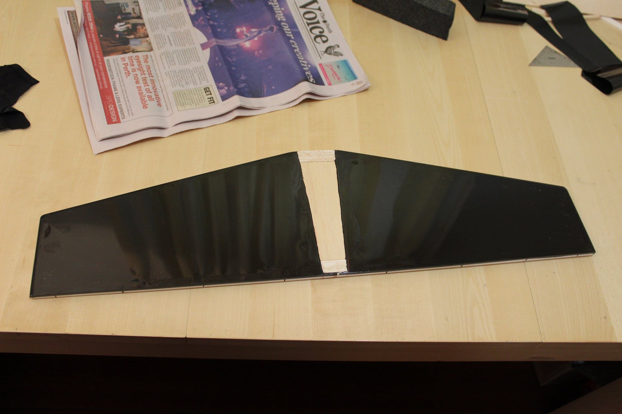
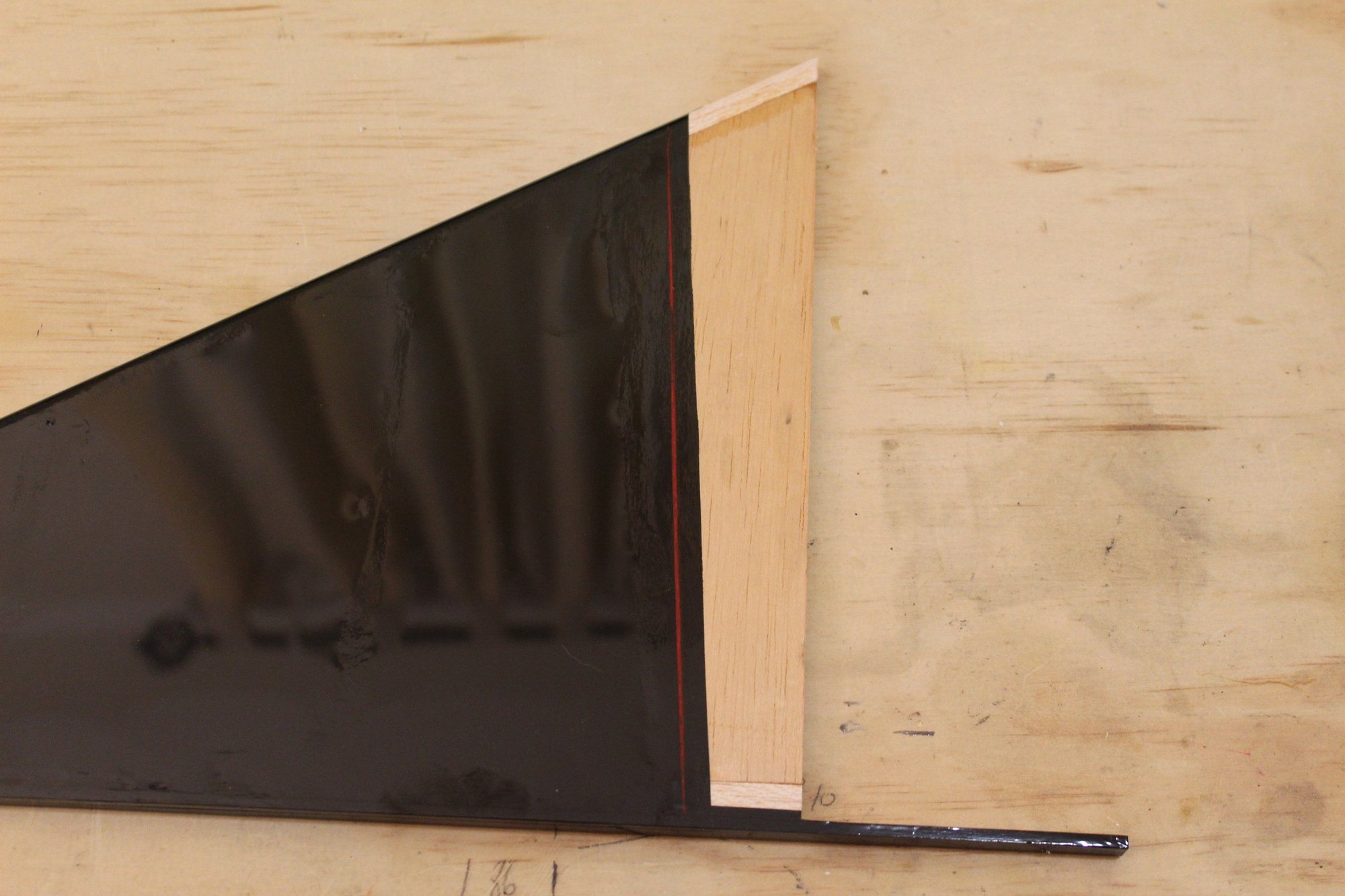
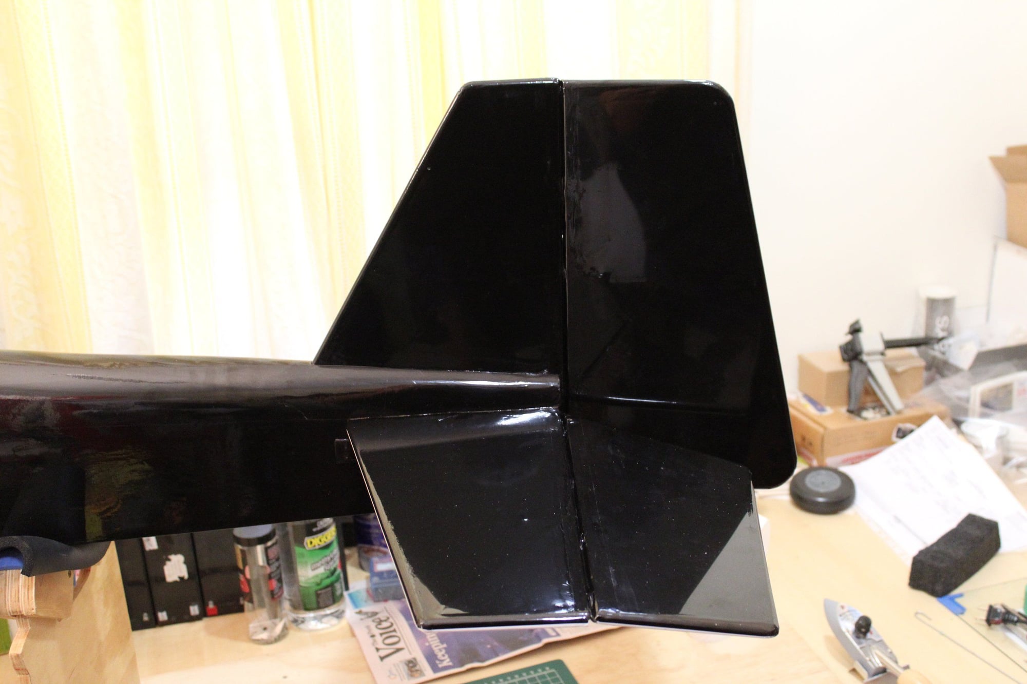
Next was removing the covering from the center of the horizontal stabiliser. I use soldering iron to "cut" covering.
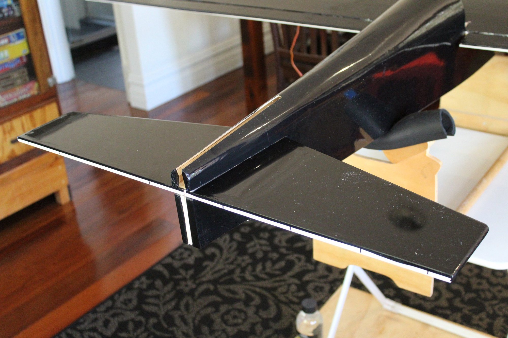
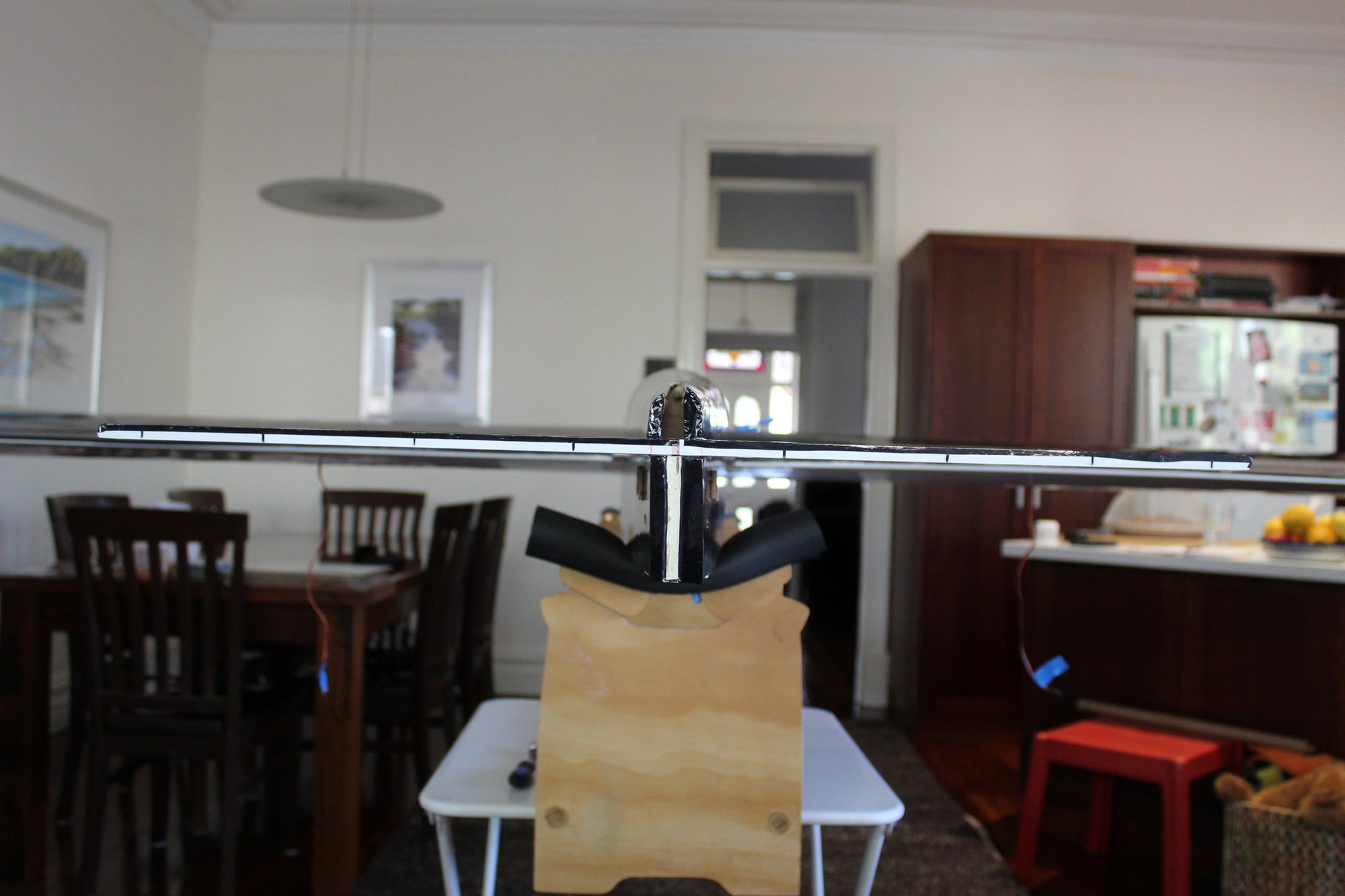
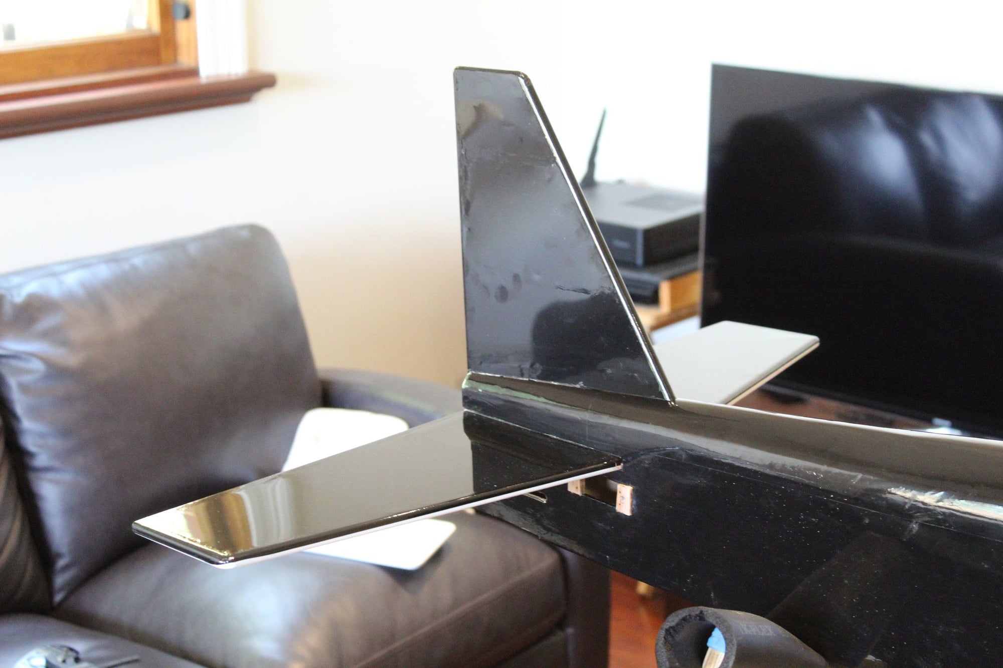
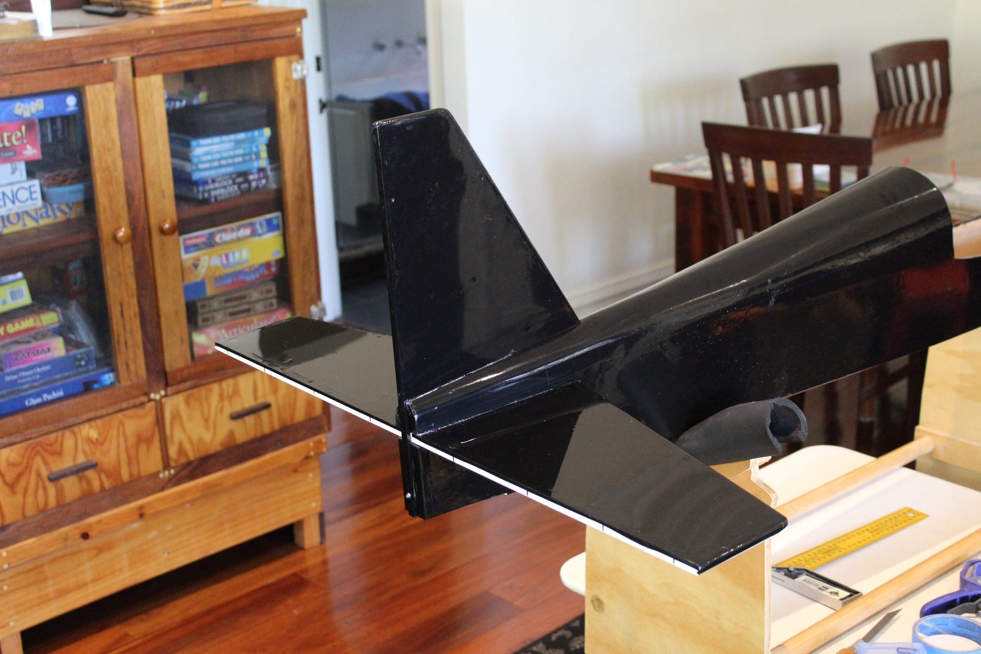
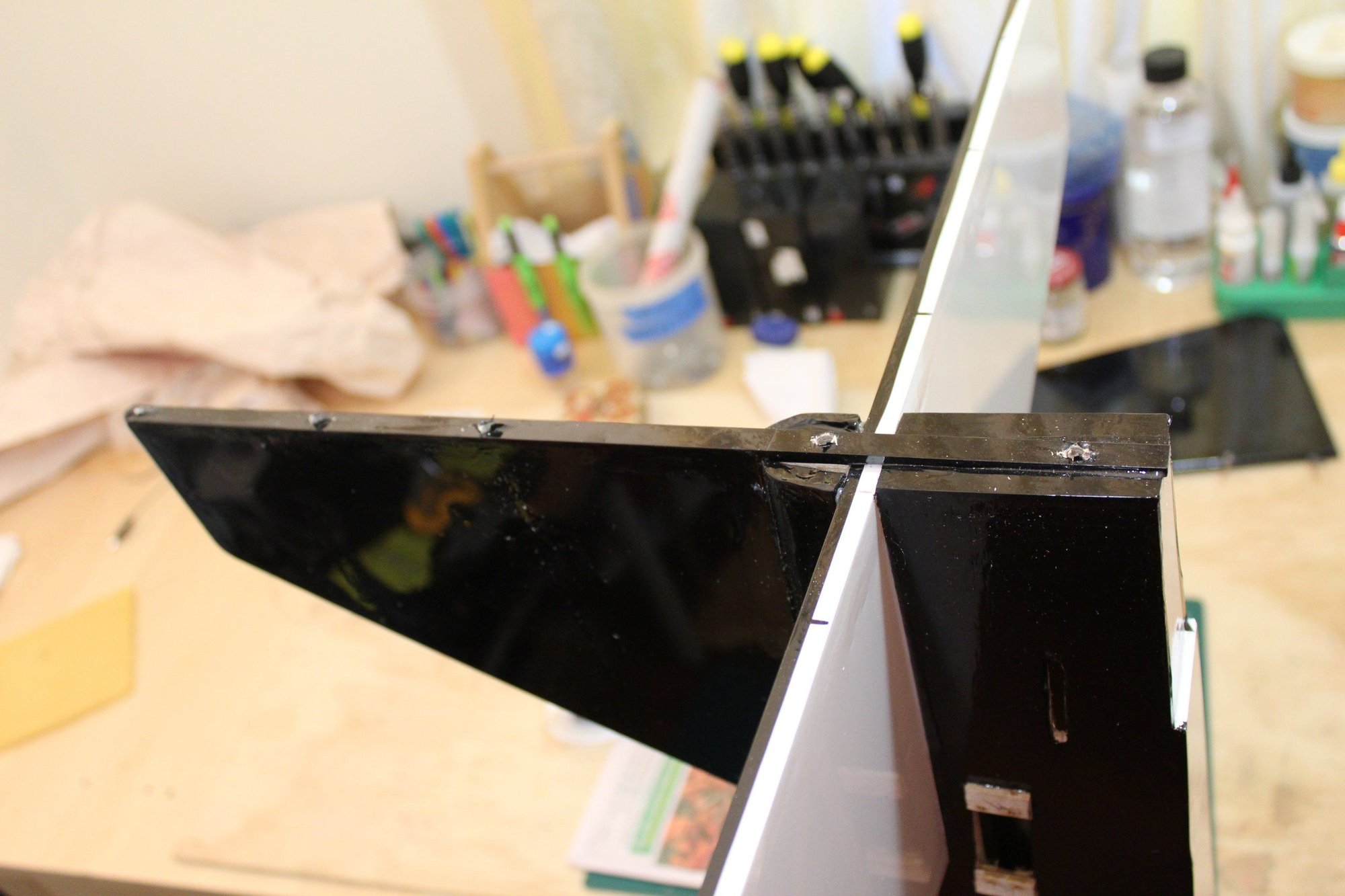
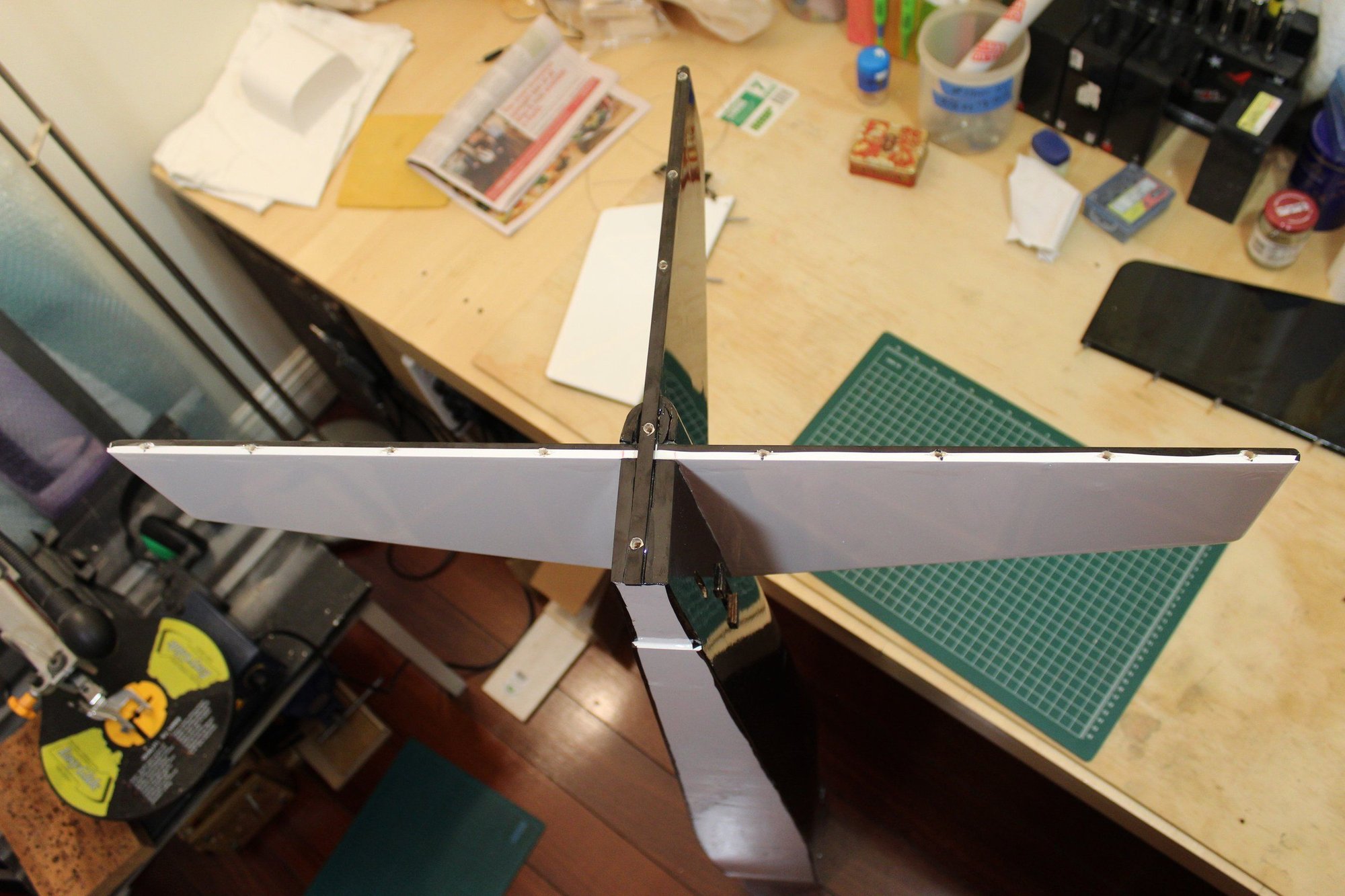
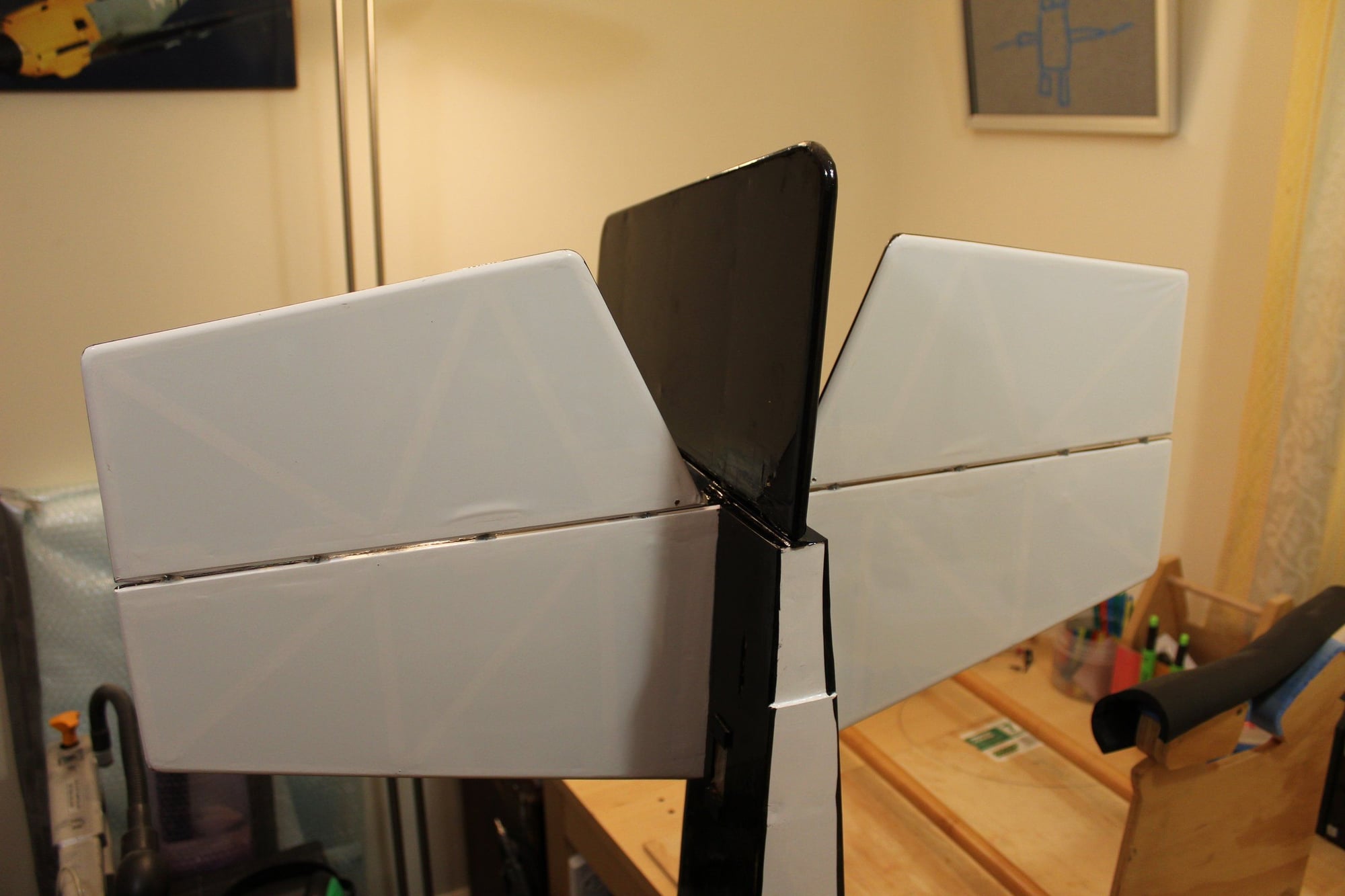
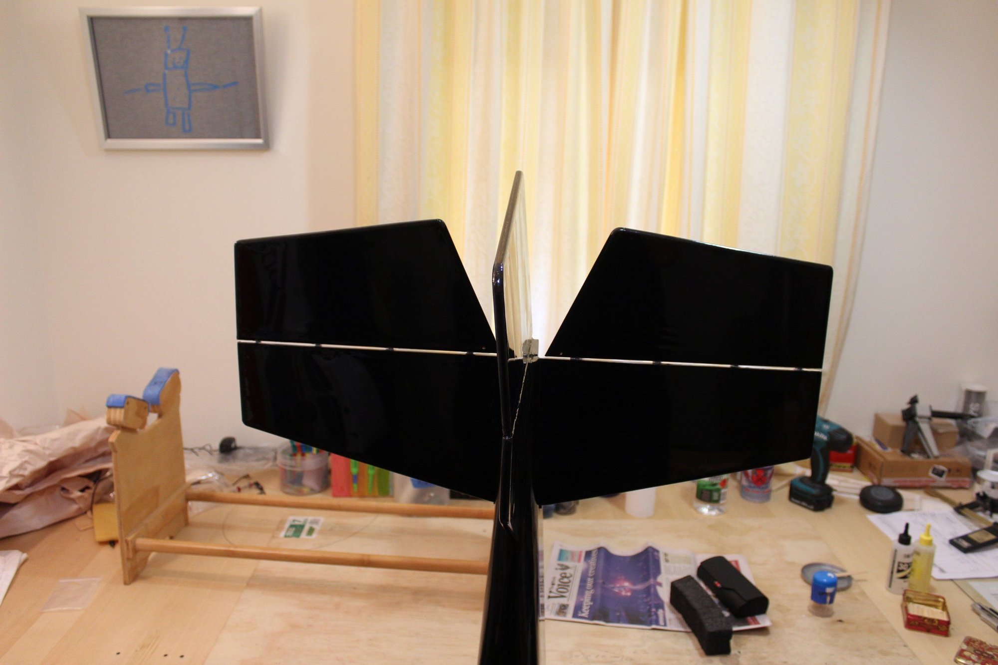
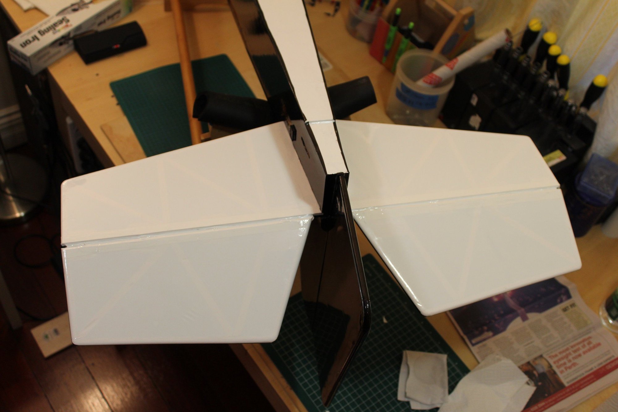
Then check, double check and triple check alignment and gluing the horizontal stabiliser into place.
Cheers,
Eran
Next was removing the covering from the center of the horizontal stabiliser. I use soldering iron to "cut" covering.
Then check, double check and triple check alignment and gluing the horizontal stabiliser into place.
Cheers,
Eran
02-09-2024, 10:59 PM
#78
Thread Starter
Join Date: Jun 2008
Location: Perth WA, AUSTRALIA
Posts: 1,208
Likes: 0
Received 12 Likes
on
12 Posts
Back to tackling the fibreglass parts, my friend Glenn kindly offered to coach me through. We will be making together the section where the cockpit is (which should be the most difficult part to make with the bottom half of the cowl). Glenn will be making the other half of the cowl later in the (the cowl mold was made by Glenn earlier).
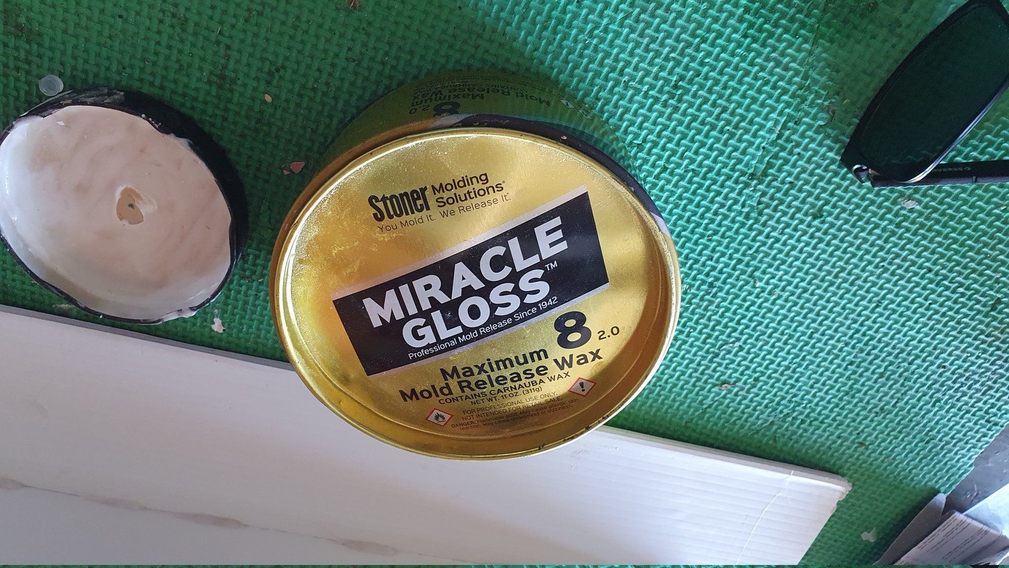
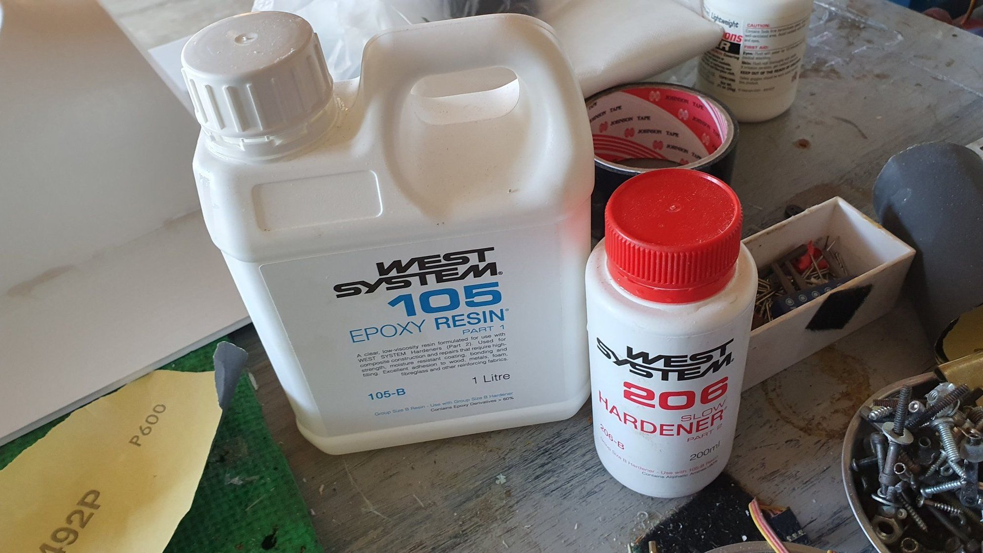
The ABS part was hot-glued to a plastic sign material base to allow moving it around during the work. We were using mold release wax (5 coats on the ABS plastic) and Glenn is using West Systems fibreglass resin. Unfortunately, as we were working in Glenn's place and the resin is very messy, I do not have photos of actually laying the fibreglass over the ABS mold.
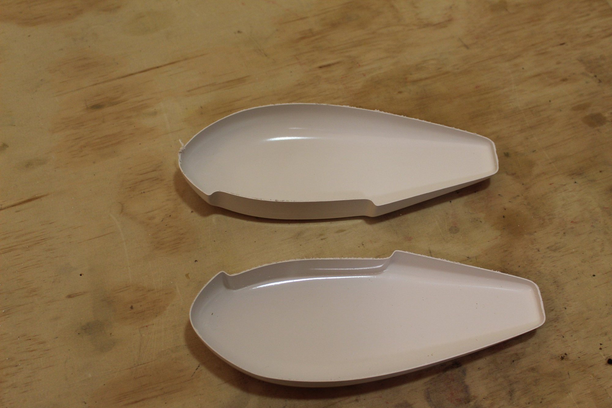
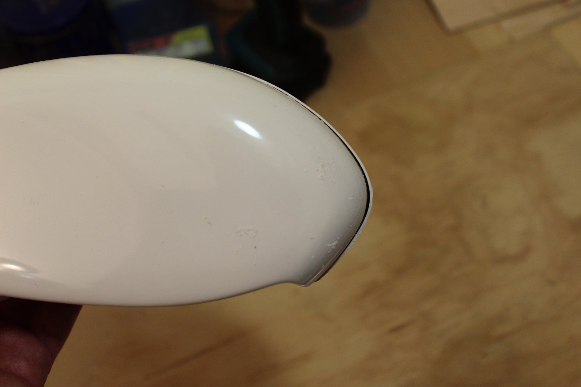
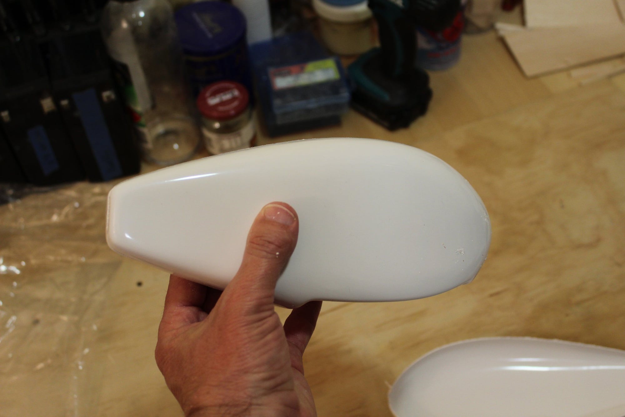
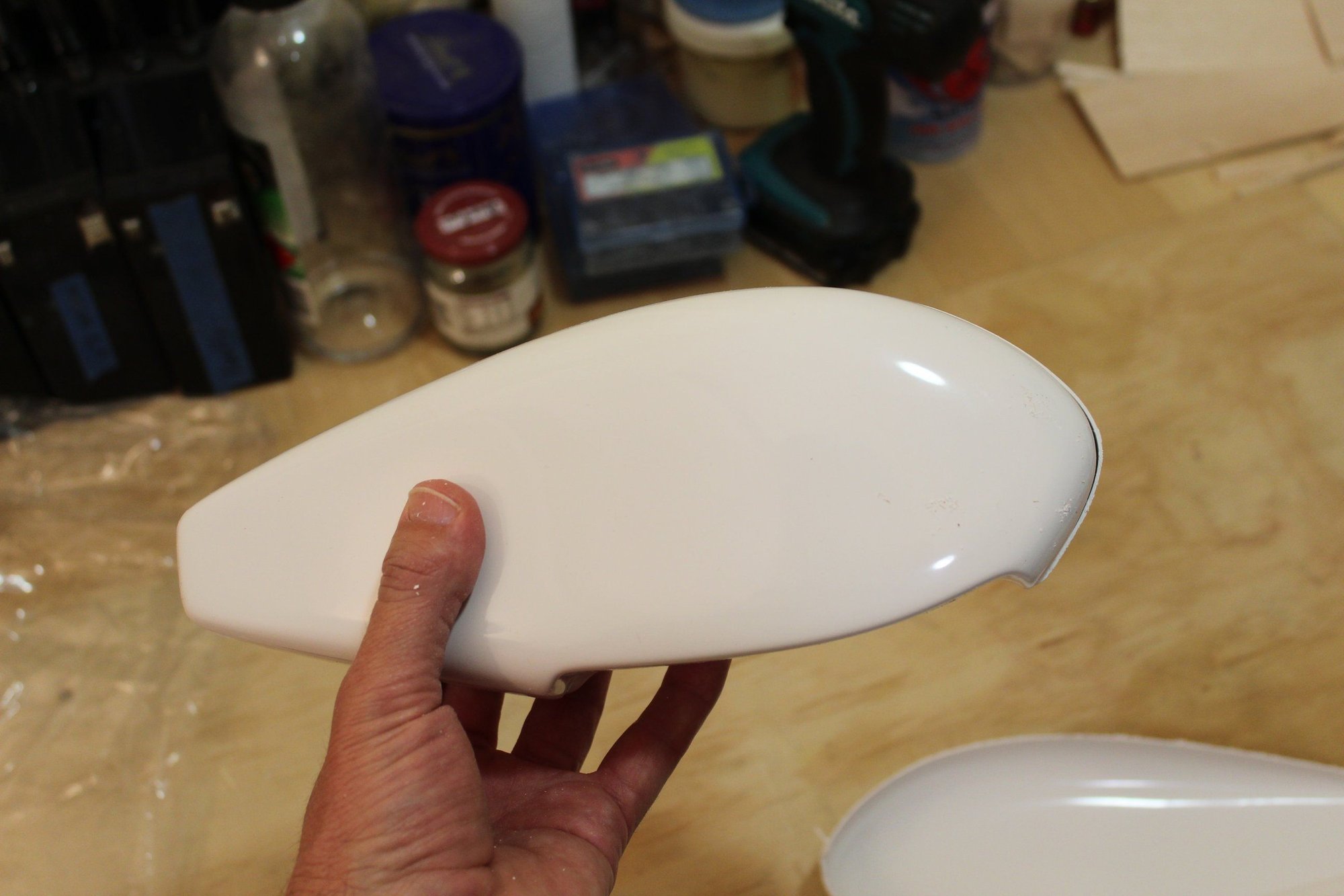
When I got home, I had a look at the wheel pants ABS parts trying to find a matching pair to be used as a mold. None of the right / left pair will match correctly... I will have to think about what to do.
Cheers,
Eran
The ABS part was hot-glued to a plastic sign material base to allow moving it around during the work. We were using mold release wax (5 coats on the ABS plastic) and Glenn is using West Systems fibreglass resin. Unfortunately, as we were working in Glenn's place and the resin is very messy, I do not have photos of actually laying the fibreglass over the ABS mold.
When I got home, I had a look at the wheel pants ABS parts trying to find a matching pair to be used as a mold. None of the right / left pair will match correctly... I will have to think about what to do.
Cheers,
Eran

 02-15-2024, 06:25 PM
#80
Thread Starter
Join Date: Jun 2008
Location: Perth WA, AUSTRALIA
Posts: 1,208
Likes: 0
Received 12 Likes
on
12 Posts
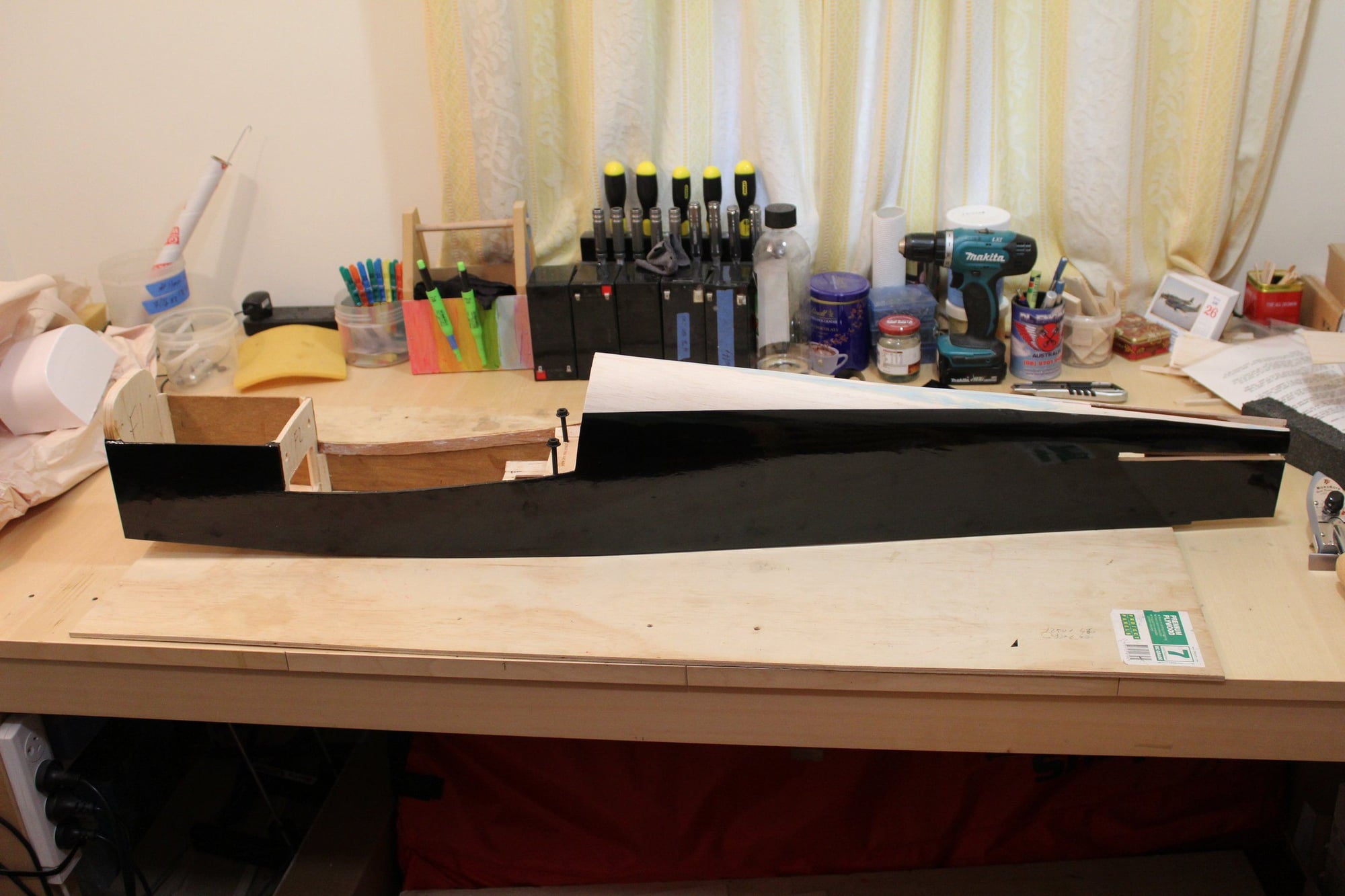
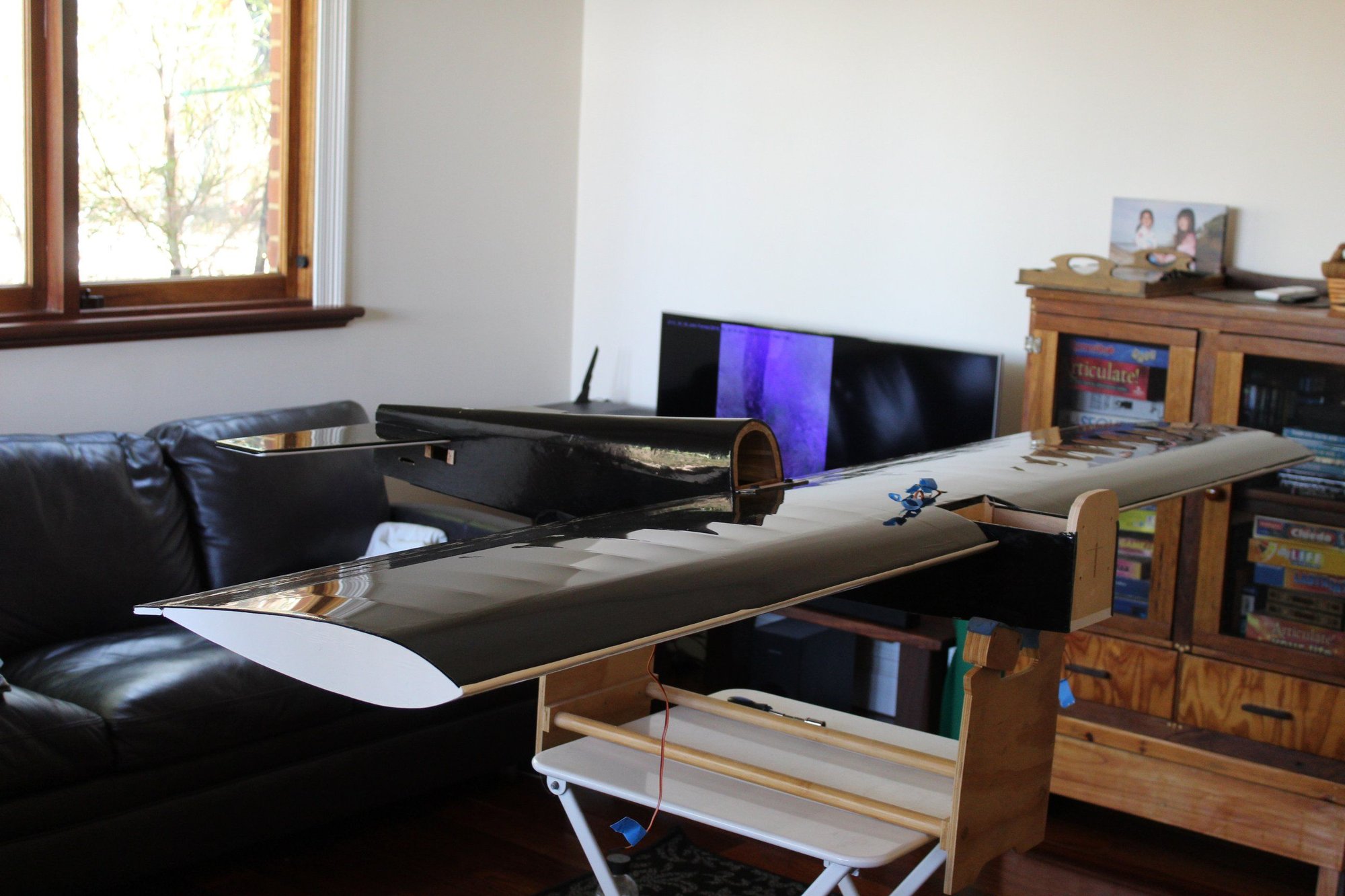
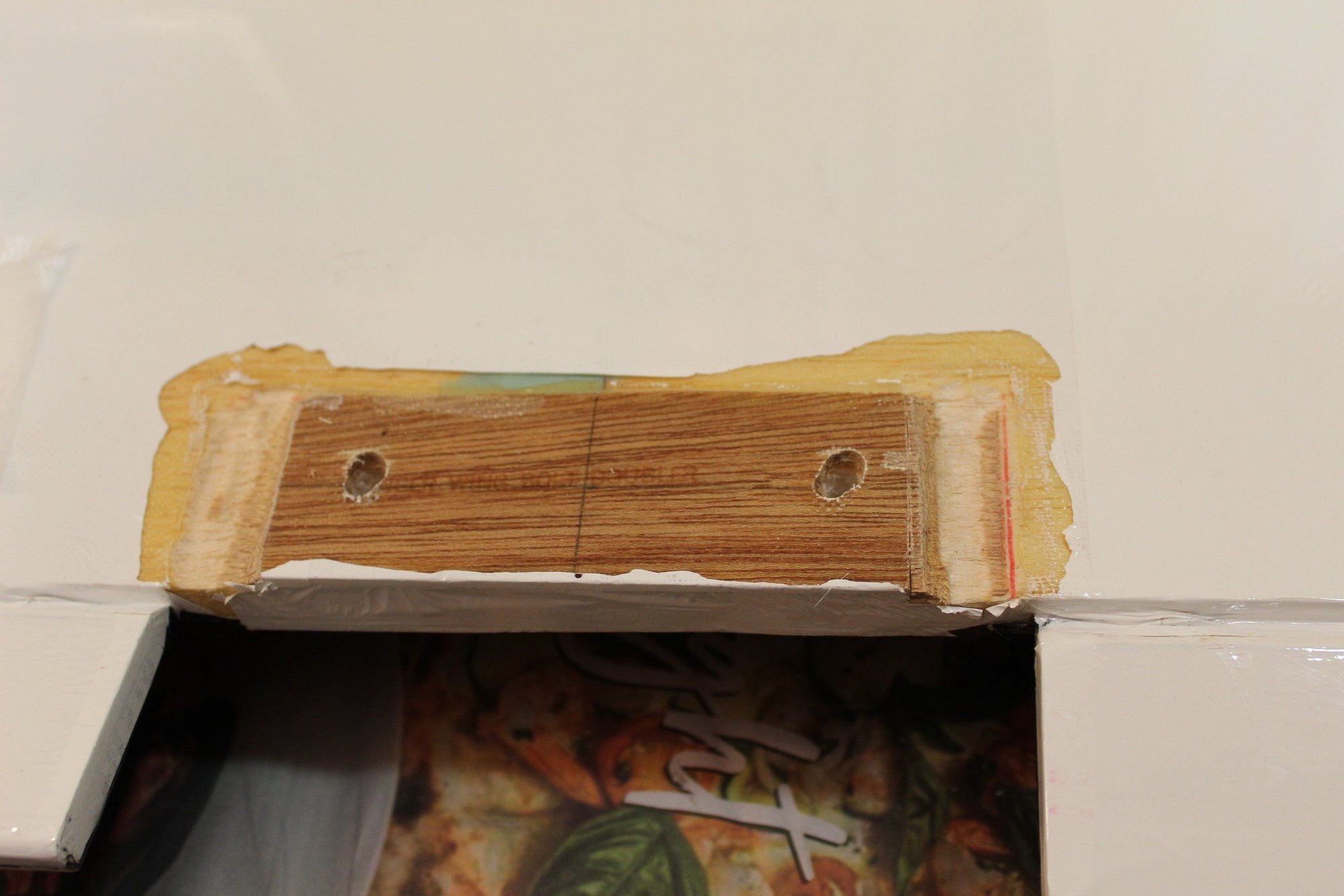
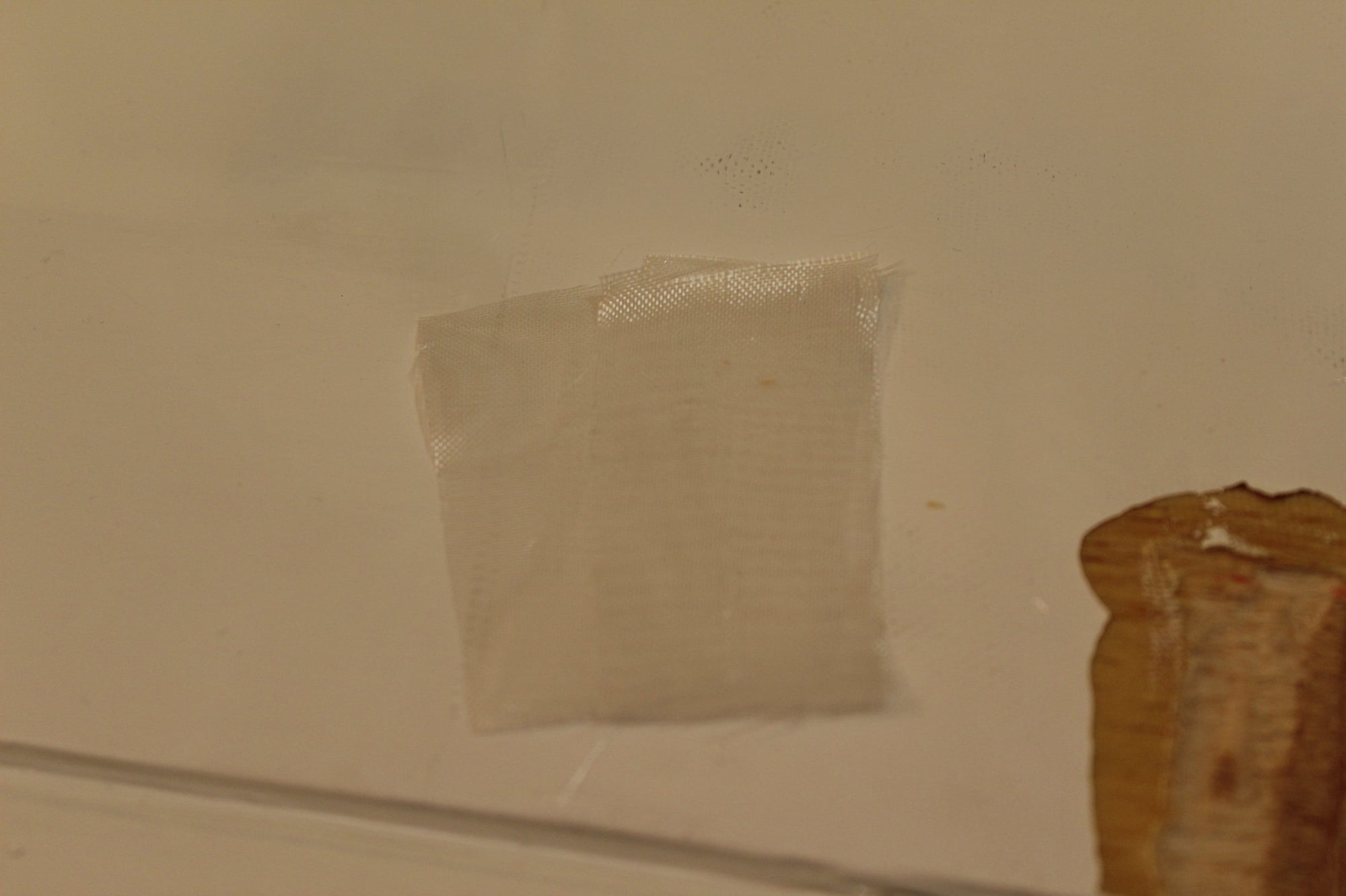
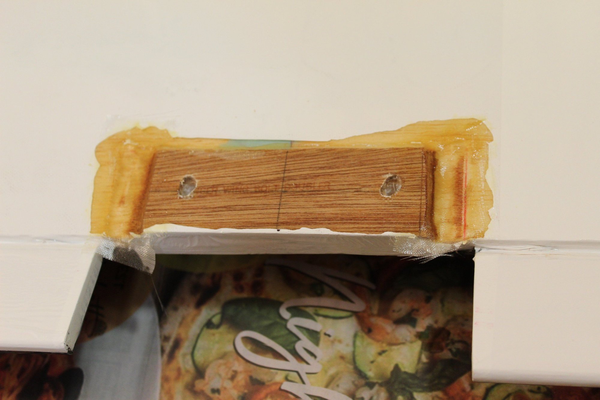
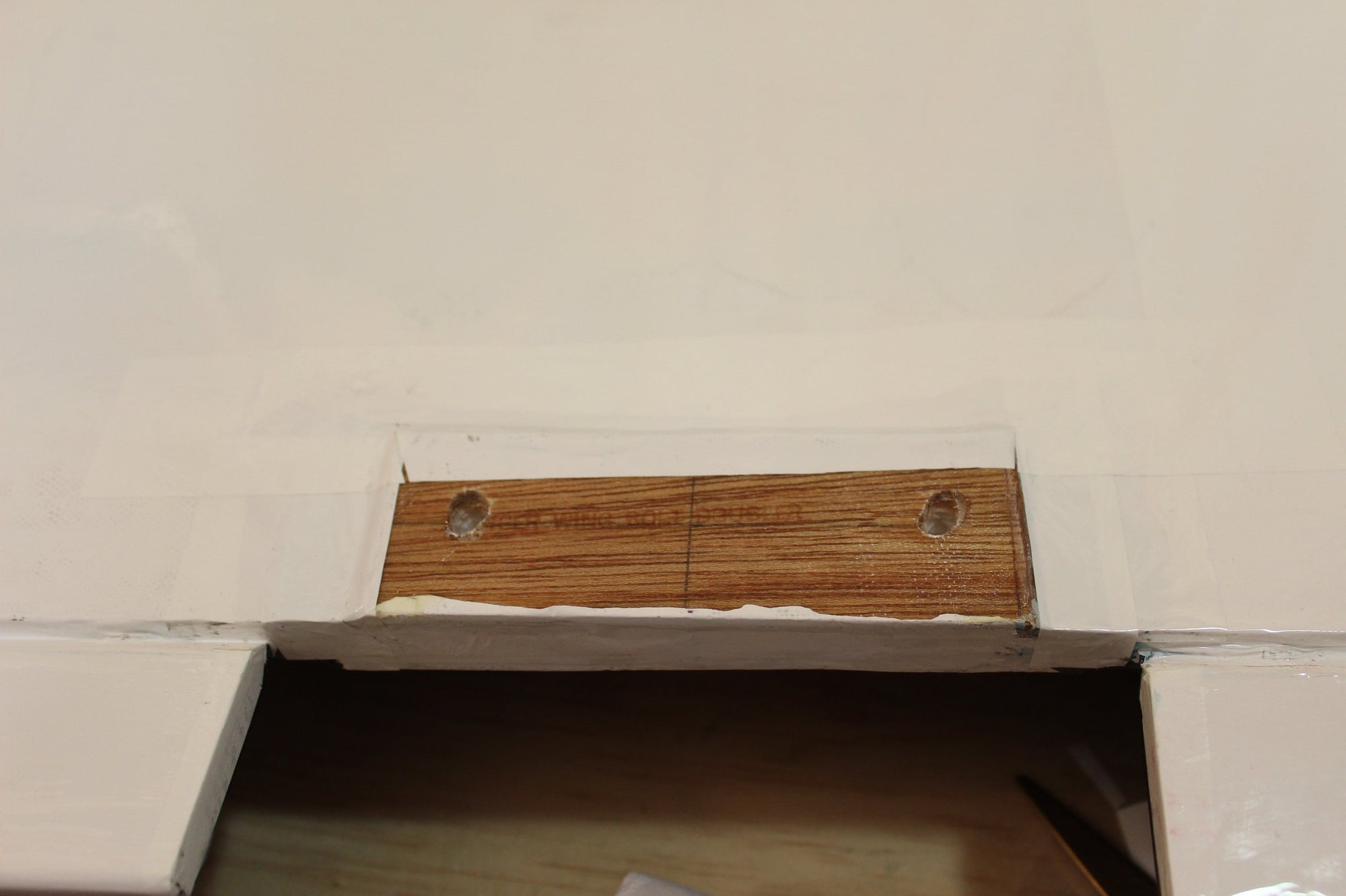
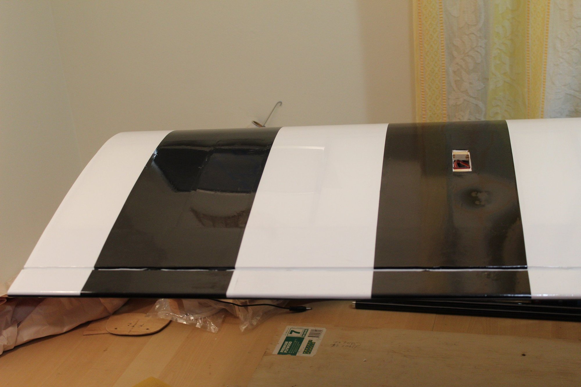
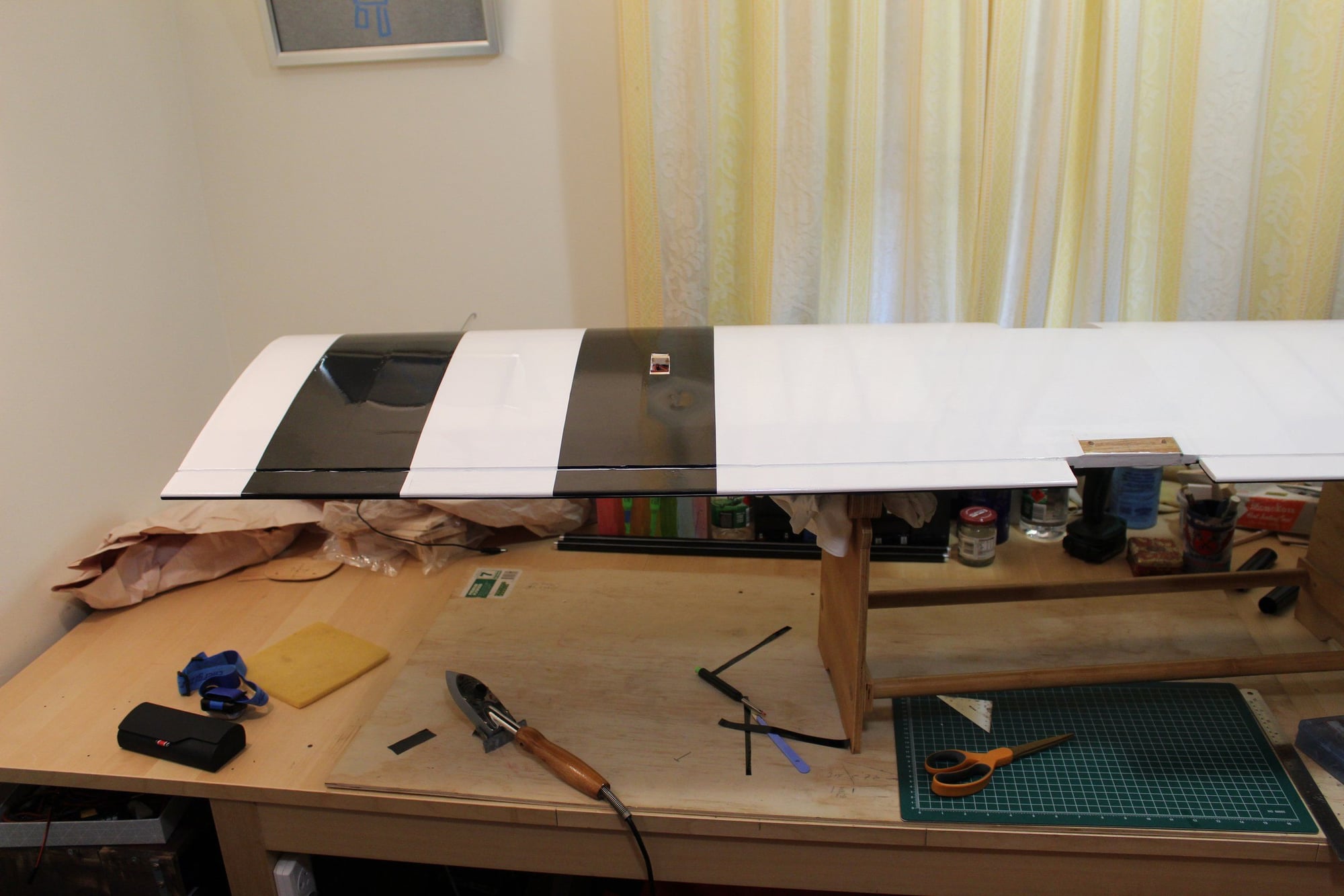
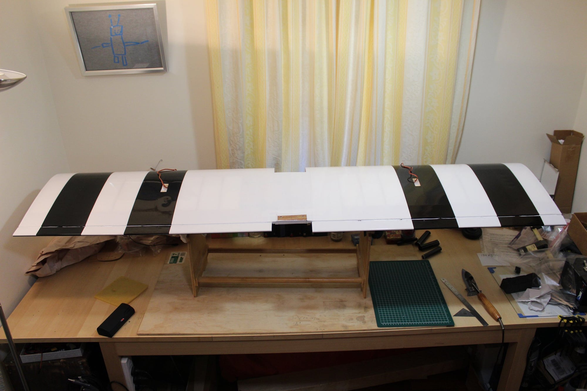
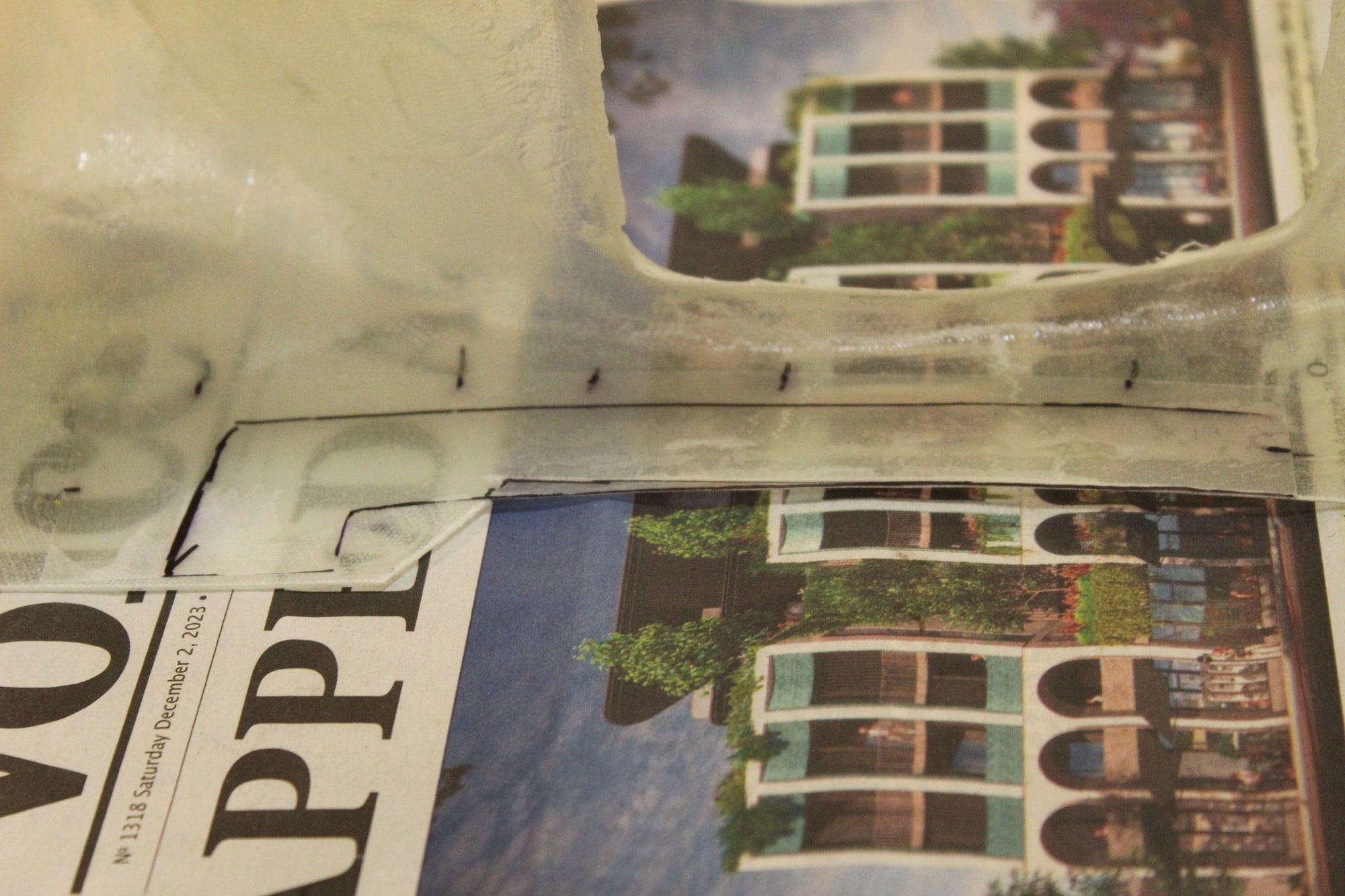
I repaired my mistake with the wing bolts plate, sanding it enough to fit into the fuselage and re-applied fibreglass. I then added some black stripes to the wing bottom covering.
Cheers,
Eran
Cheers,
Eran
02-17-2024, 02:43 PM
#81
Thread Starter
Join Date: Jun 2008
Location: Perth WA, AUSTRALIA
Posts: 1,208
Likes: 0
Received 12 Likes
on
12 Posts
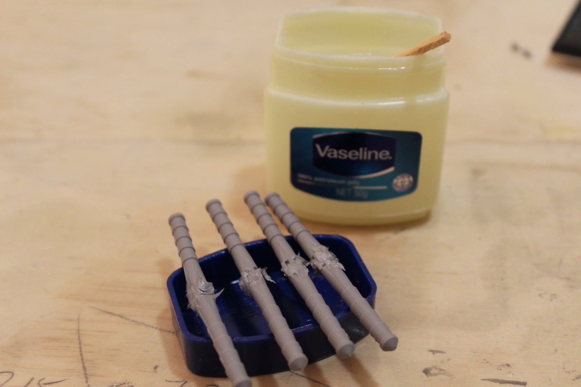
Prior to drilling for the hinges, I marked the drill to the correct depth.
I then glued the hinges to the elevators and rudder, using the Robart Super Hinge Points #310. I applied Vaseline to protect the pin area.
I also realised that I did not modify the rudder structure for using the Sullivan Super Rudder Horn (S568) instead of the horn proposed on the plan (I will be using a Pull-Pull system). I therefore glued a plywood piece in the correct distance from the leading edge and patch covered it.


Cheers,
Eran
I then glued the hinges to the elevators and rudder, using the Robart Super Hinge Points #310. I applied Vaseline to protect the pin area.
I also realised that I did not modify the rudder structure for using the Sullivan Super Rudder Horn (S568) instead of the horn proposed on the plan (I will be using a Pull-Pull system). I therefore glued a plywood piece in the correct distance from the leading edge and patch covered it.
Cheers,
Eran
 02-24-2024, 03:20 AM
#84
Thread Starter
Join Date: Jun 2008
Location: Perth WA, AUSTRALIA
Posts: 1,208
Likes: 0
Received 12 Likes
on
12 Posts
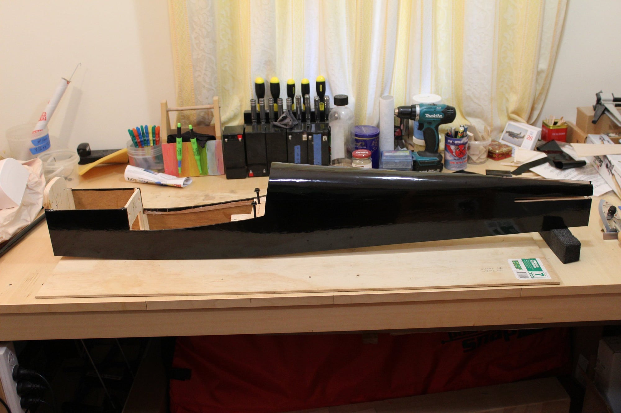
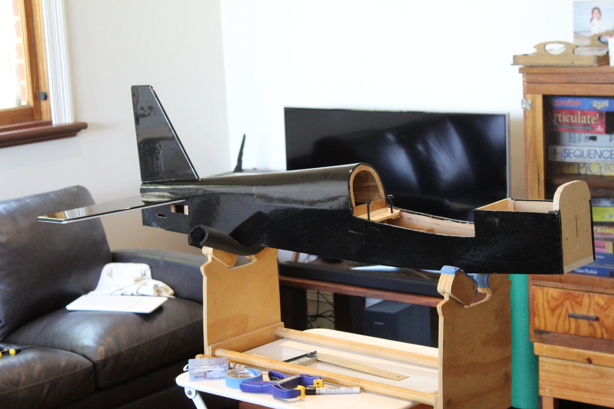
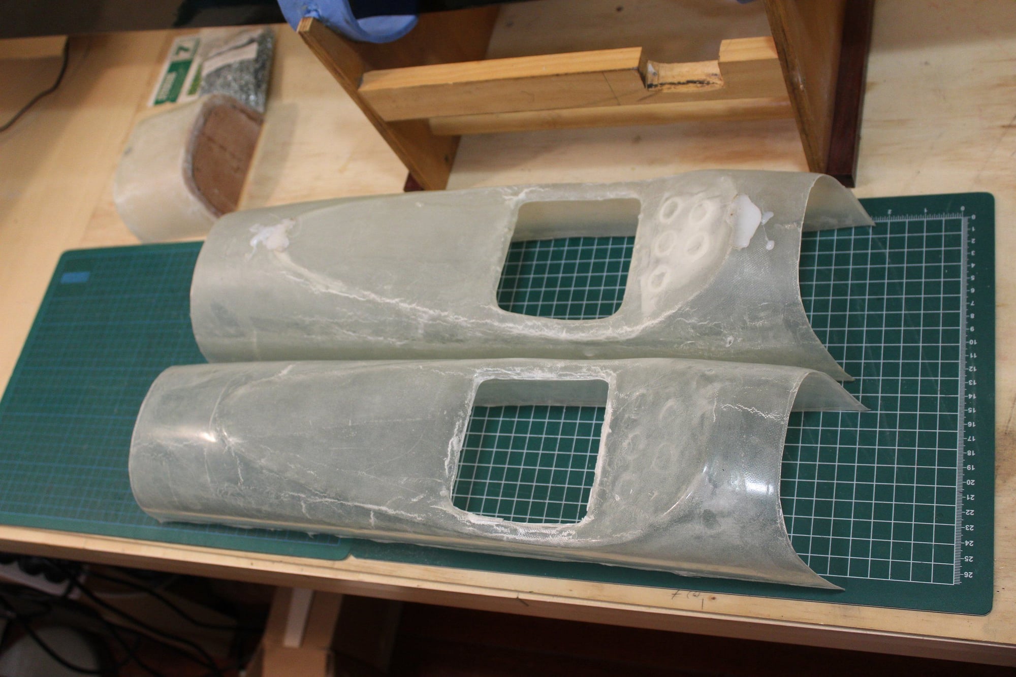
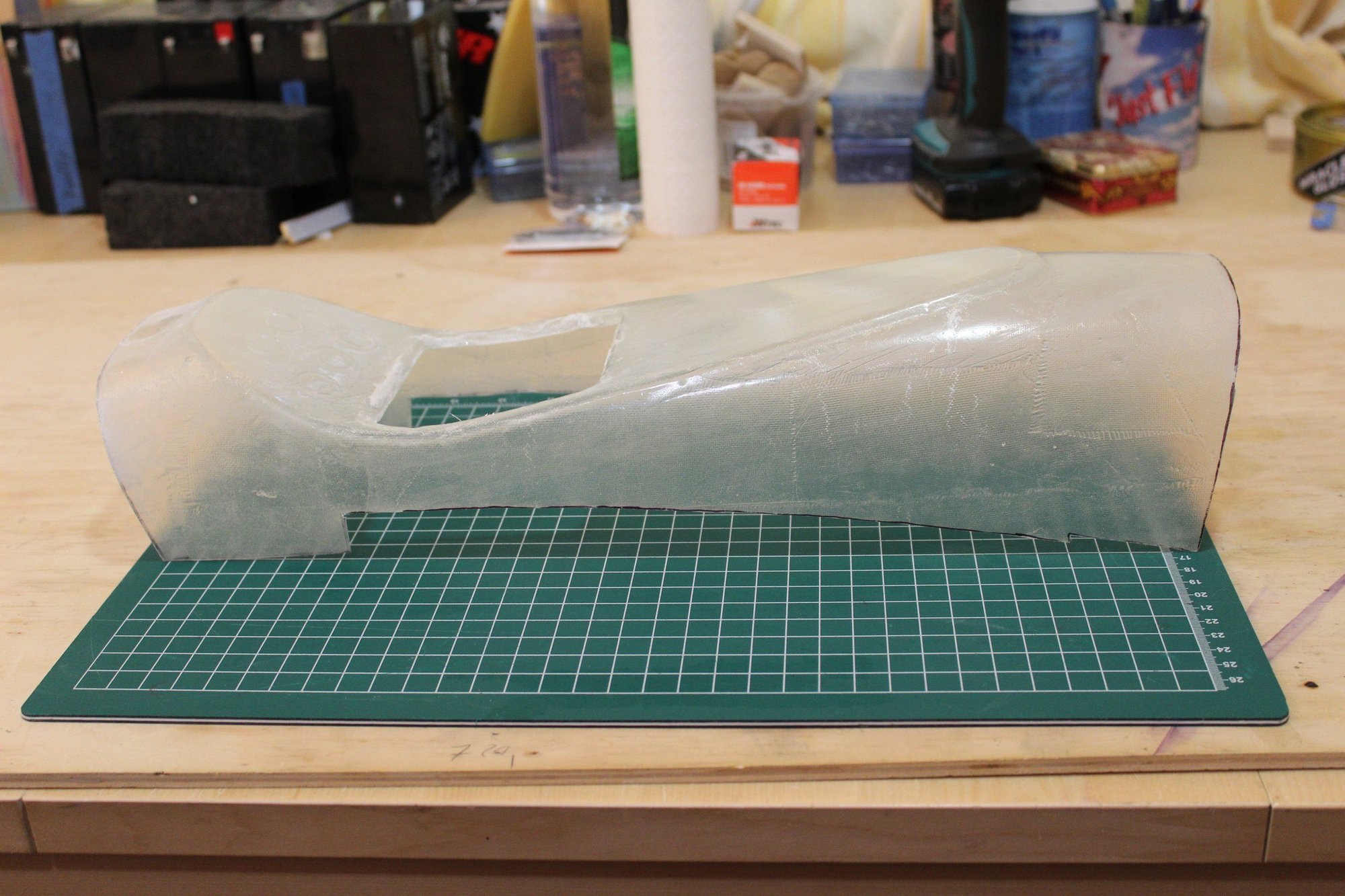
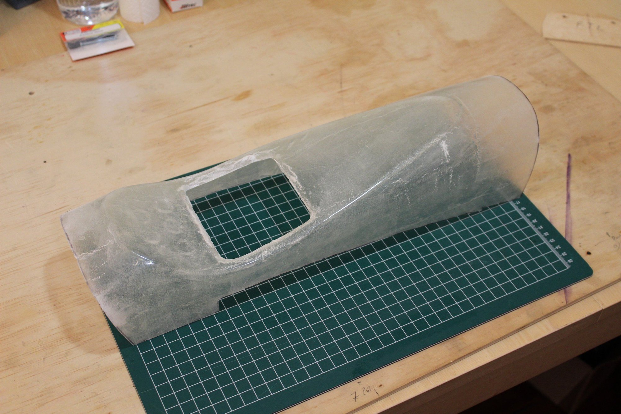
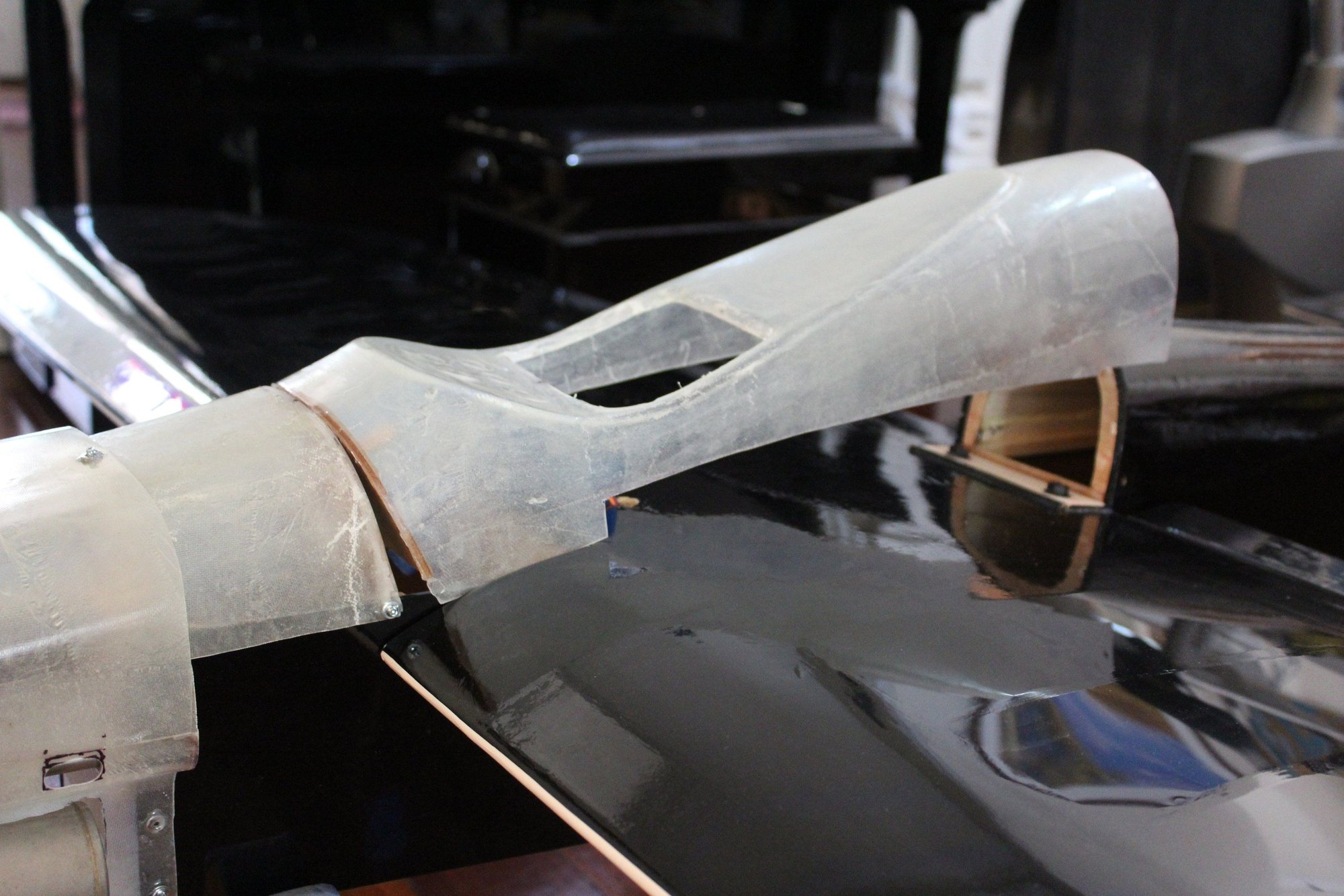
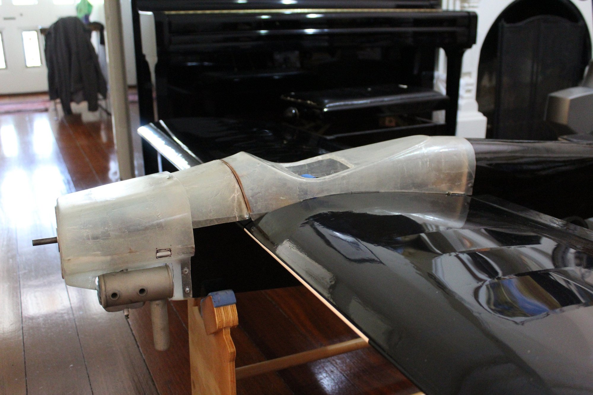
I had some time to see my friend who assisted me with the fibreglass parts. The "wing cover" and cowl were pulled out of the moulds and I am quite happy with the results, especially the cowl.
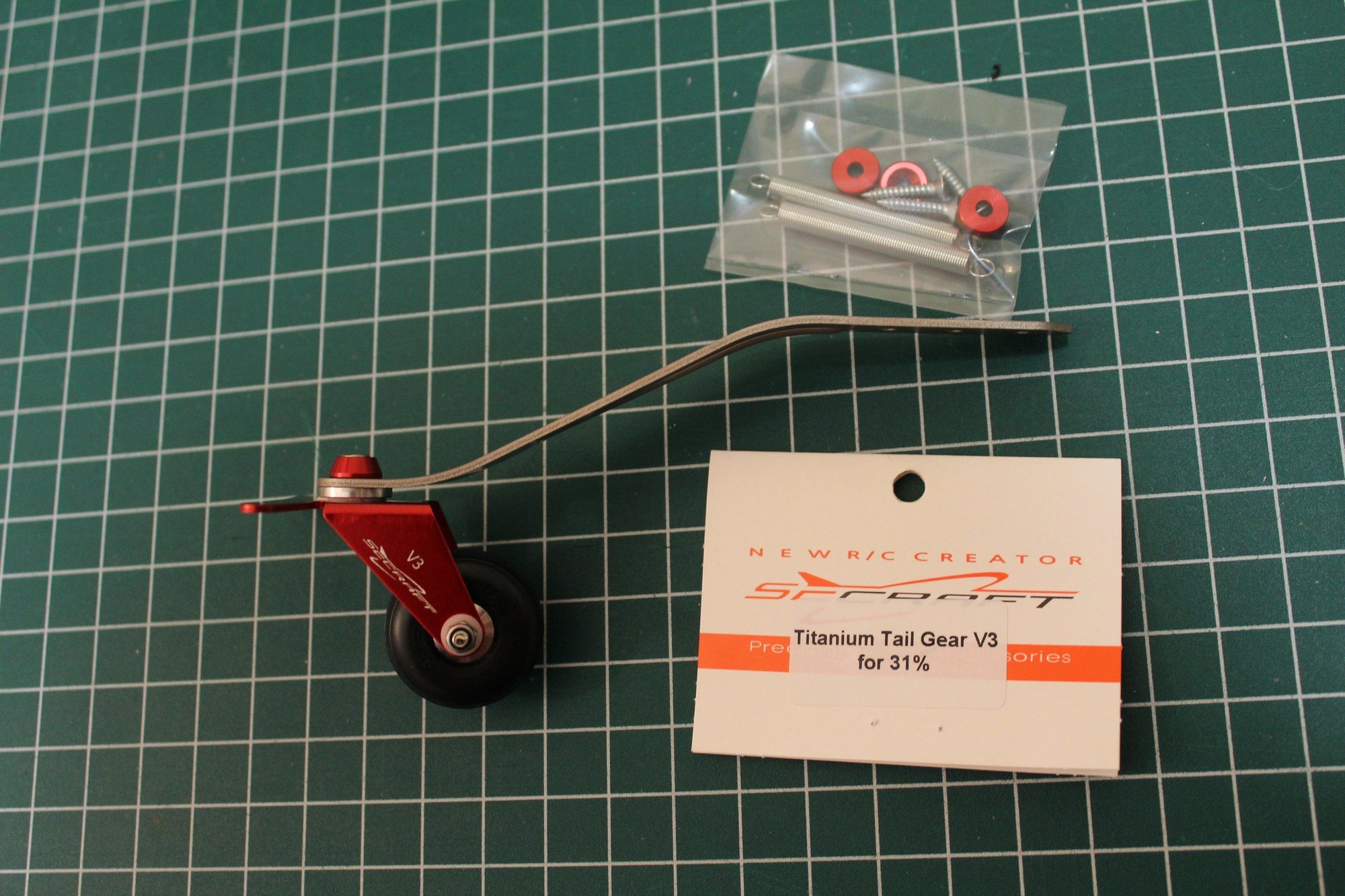
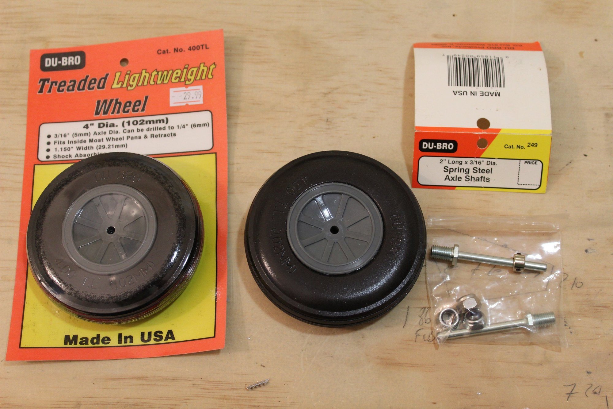
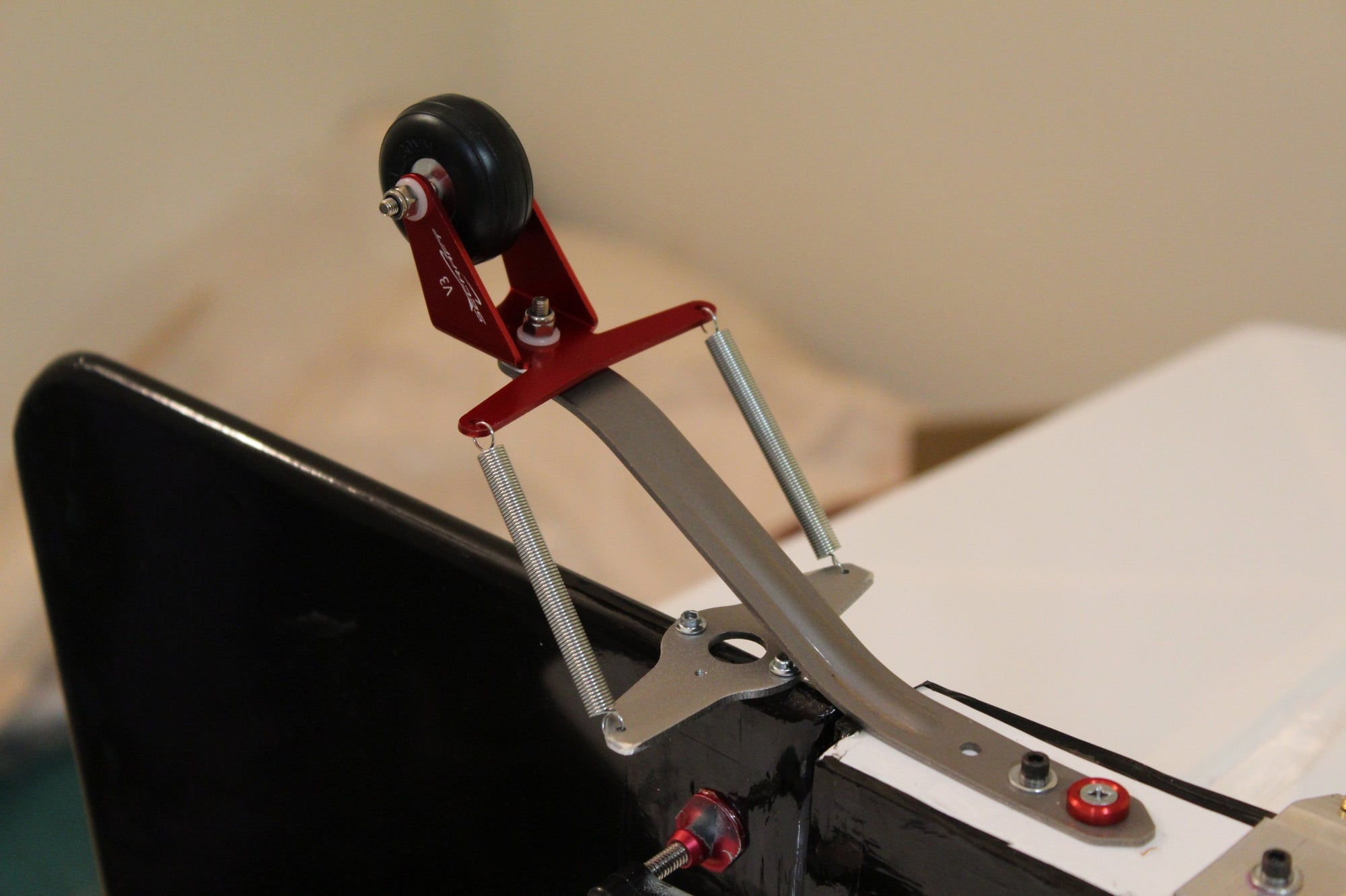
I purchased a replacement tail wheel (a Secraft product), now that Ohio Superstar refunded my payment without explanation.

Cheers,
Eran
I purchased a replacement tail wheel (a Secraft product), now that Ohio Superstar refunded my payment without explanation.
Cheers,
Eran
02-26-2024, 04:05 AM
#85
Thread Starter
Join Date: Jun 2008
Location: Perth WA, AUSTRALIA
Posts: 1,208
Likes: 0
Received 12 Likes
on
12 Posts
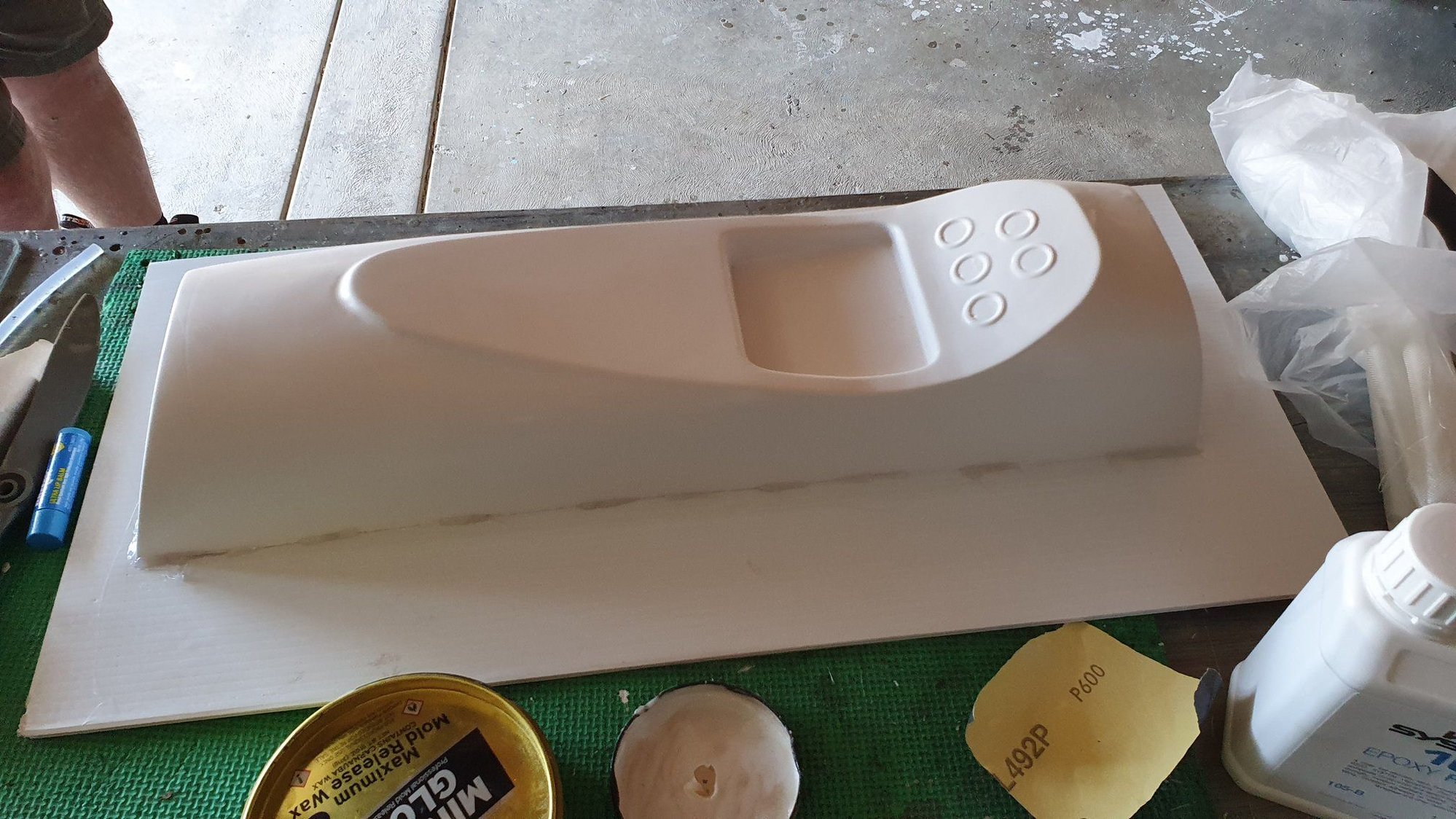
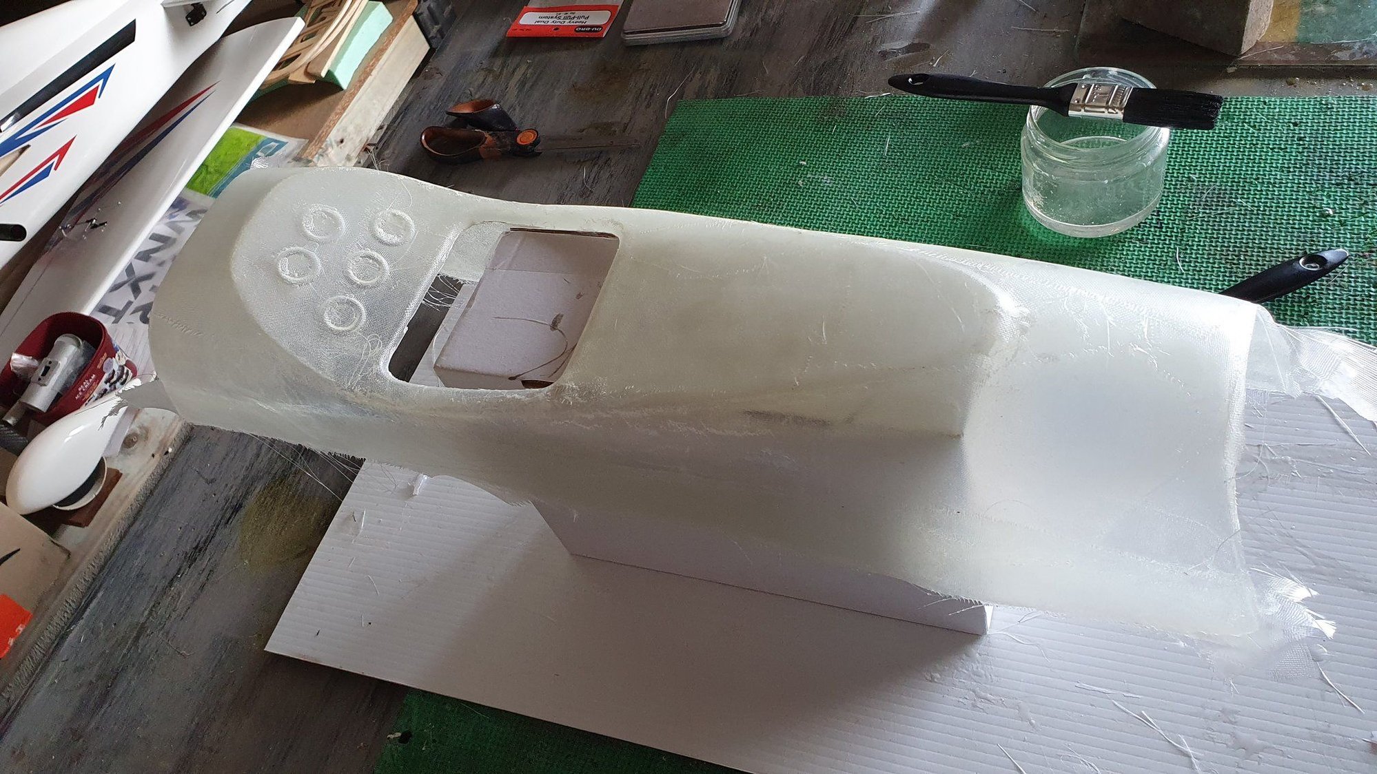
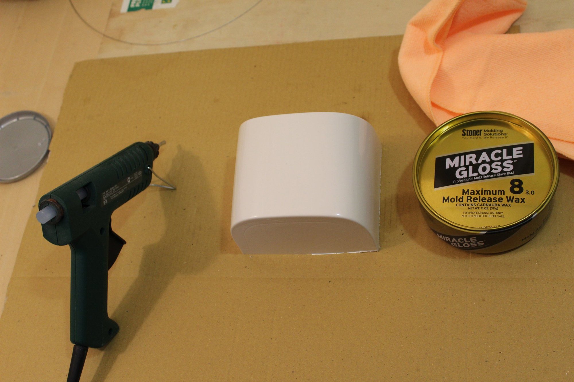
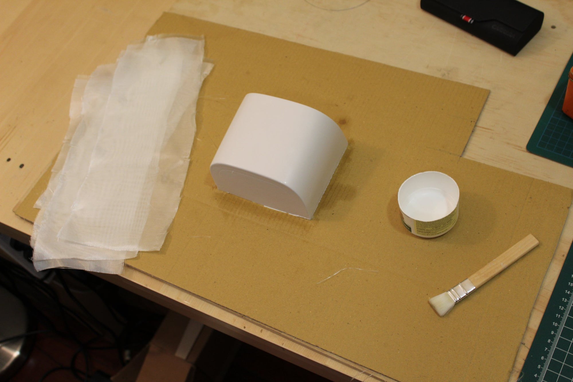
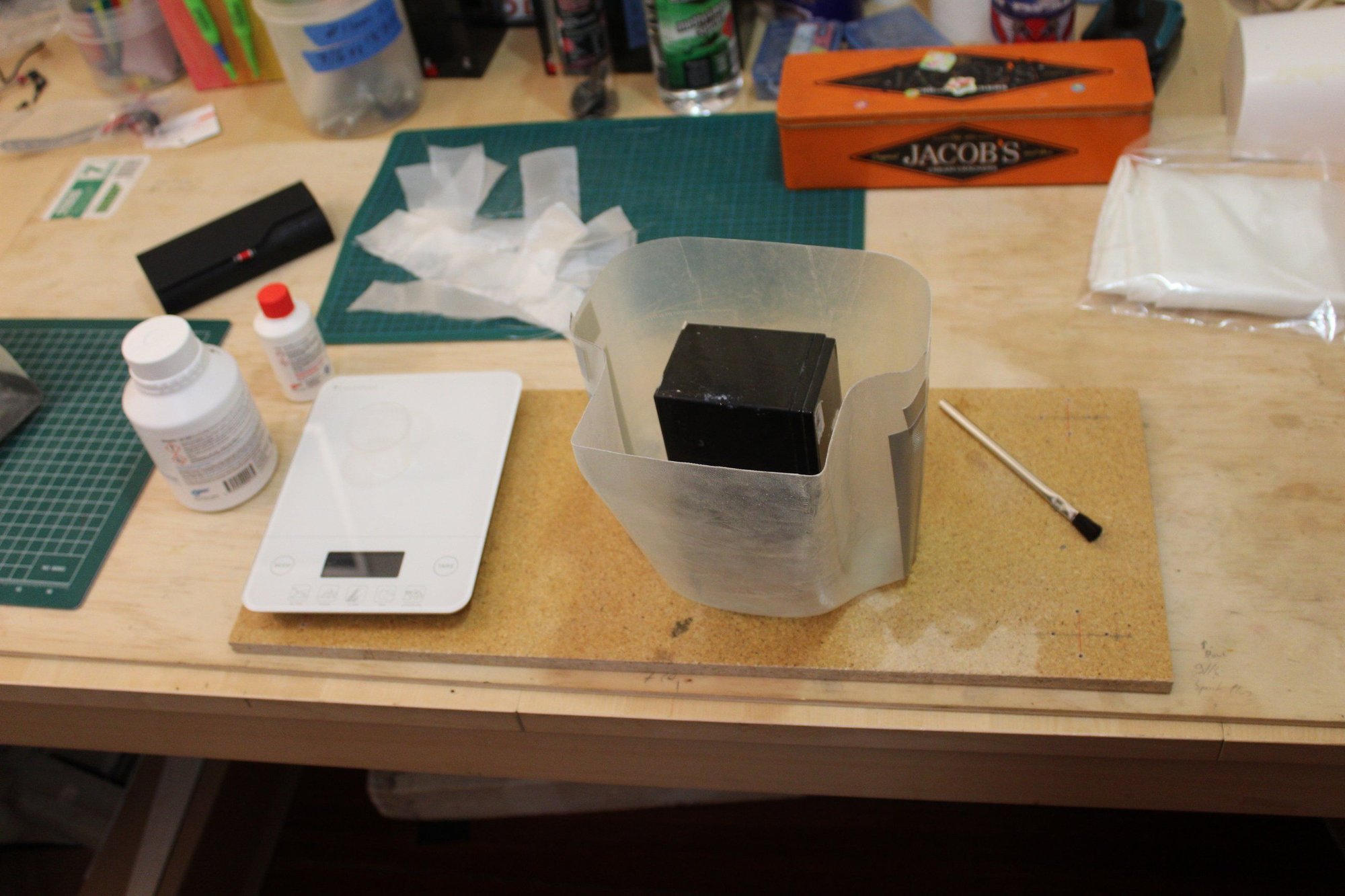
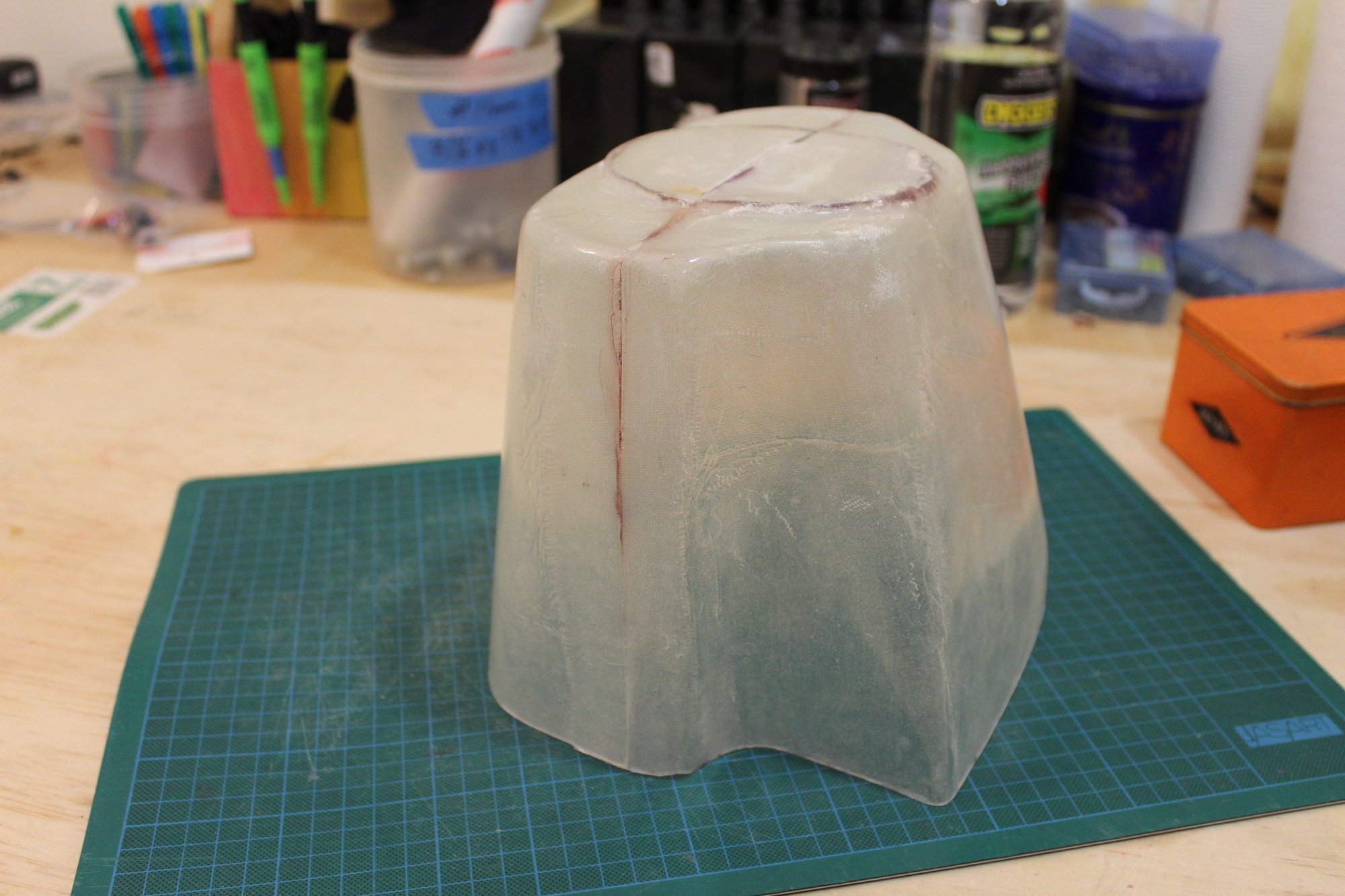
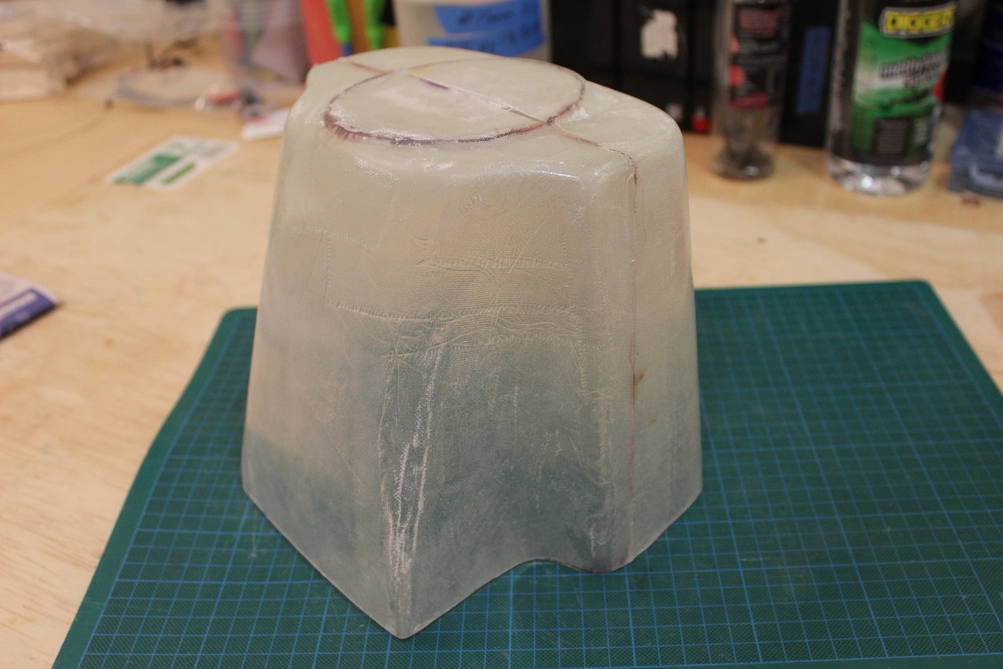
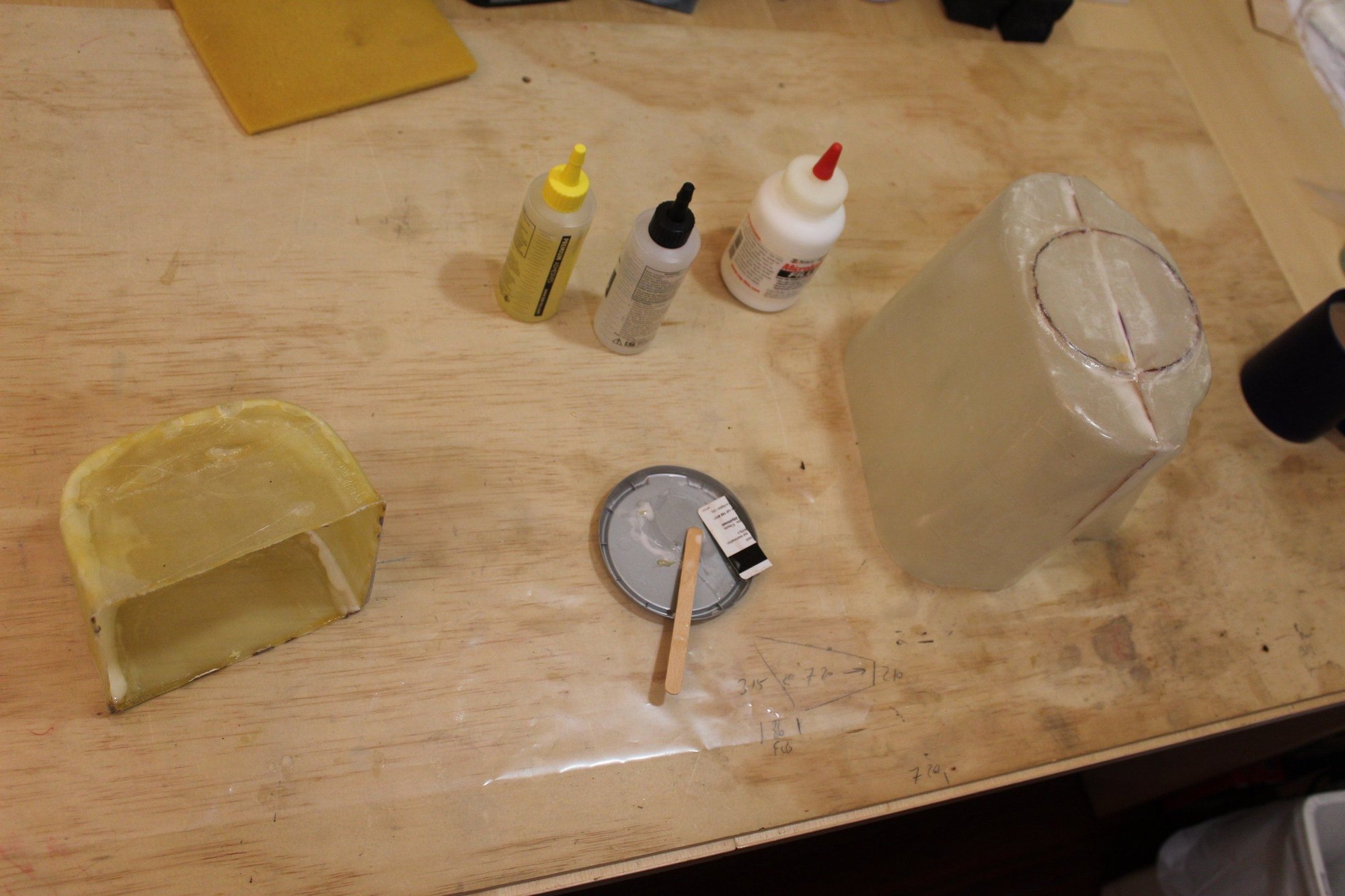
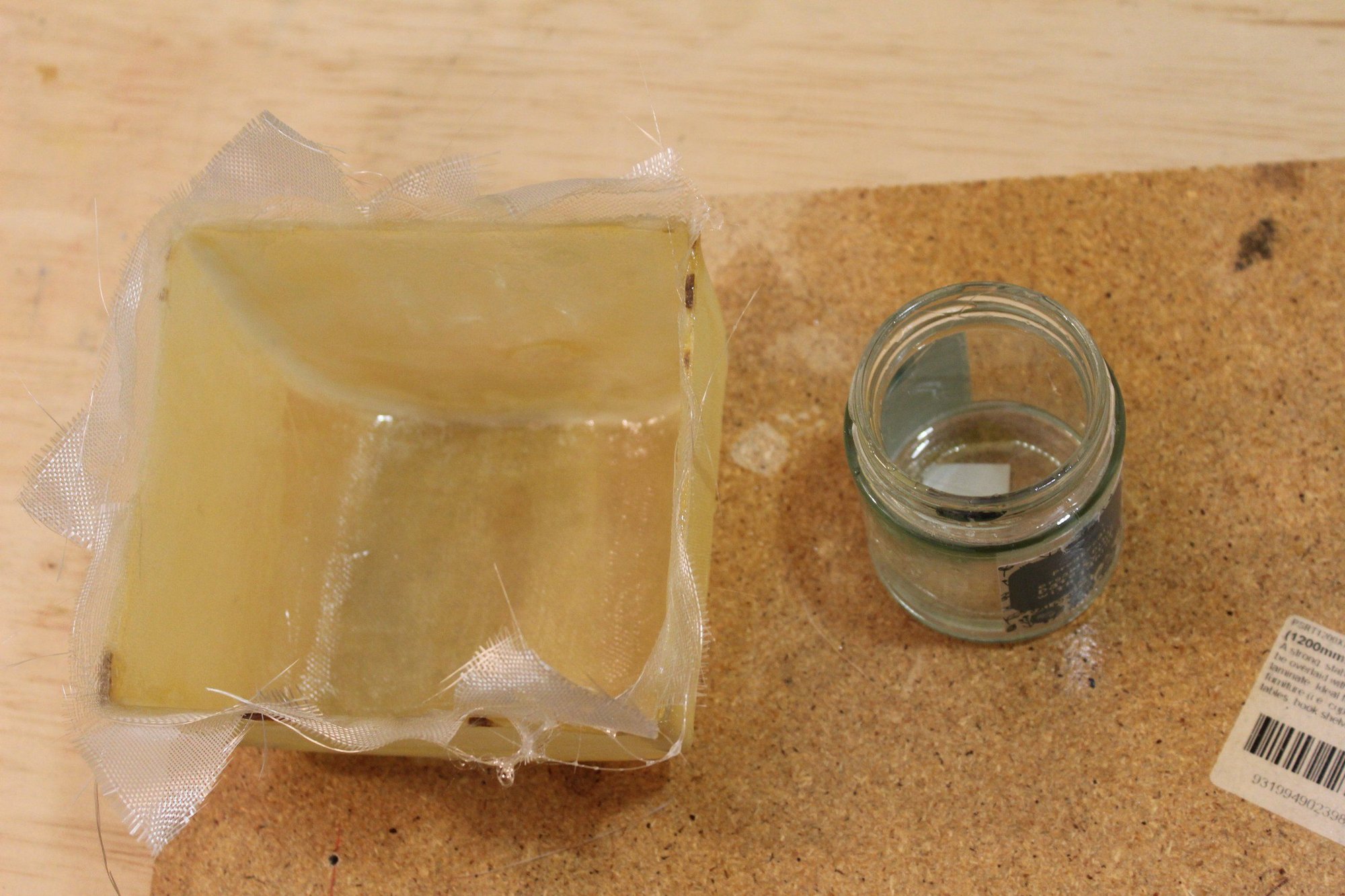
implementing what I learned from my friend, I used the ABS plastic tank cover to make a fibreglass mould. I hot glued it to cardboard to make handling easier.
While waiting for the resin to dry, I trimmed the cowl parts.


Cheers,
Eran
While waiting for the resin to dry, I trimmed the cowl parts.
Cheers,
Eran
02-28-2024, 02:43 AM
#86
Thread Starter
Join Date: Jun 2008
Location: Perth WA, AUSTRALIA
Posts: 1,208
Likes: 0
Received 12 Likes
on
12 Posts
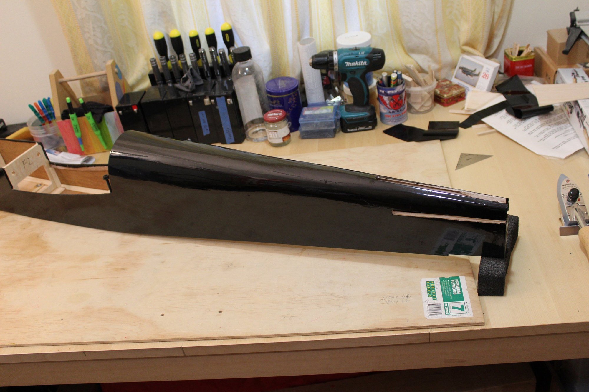
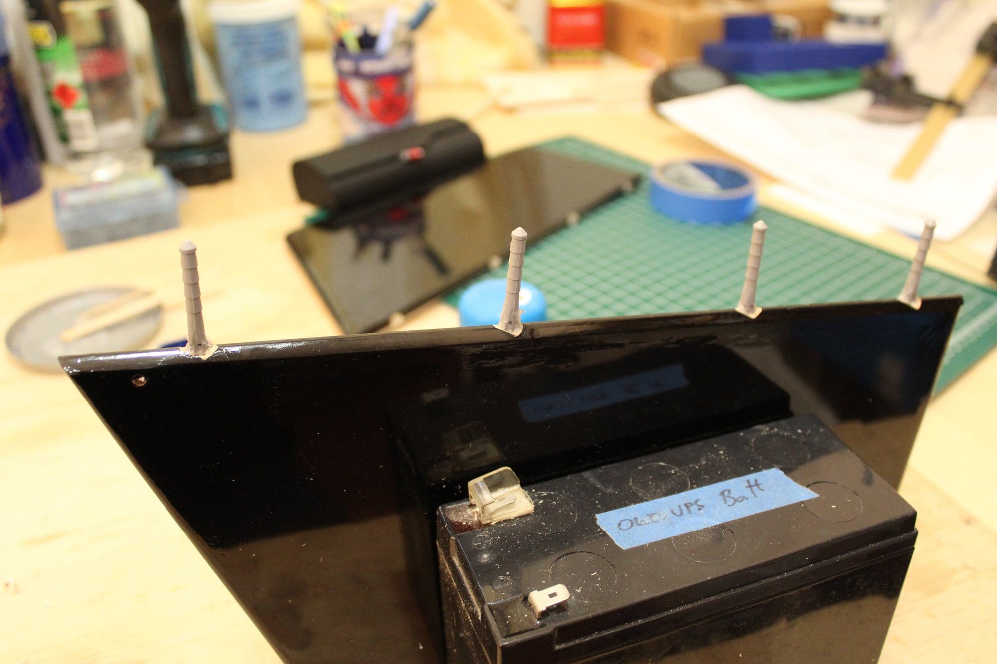
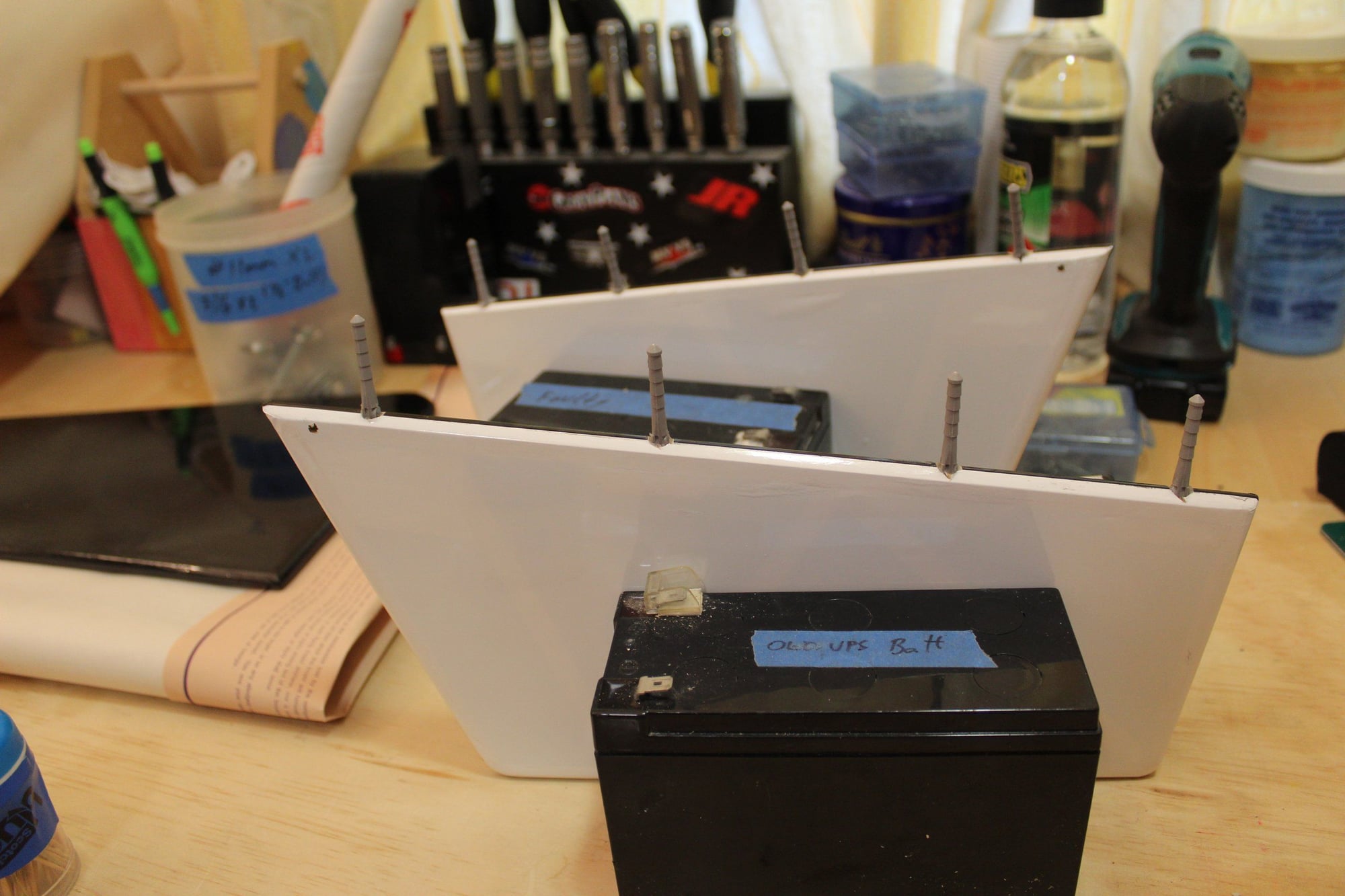
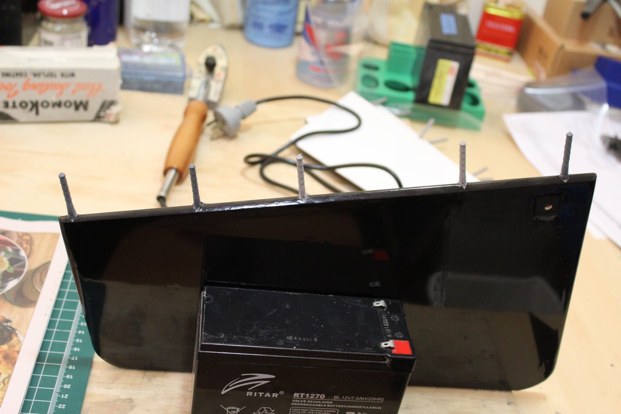
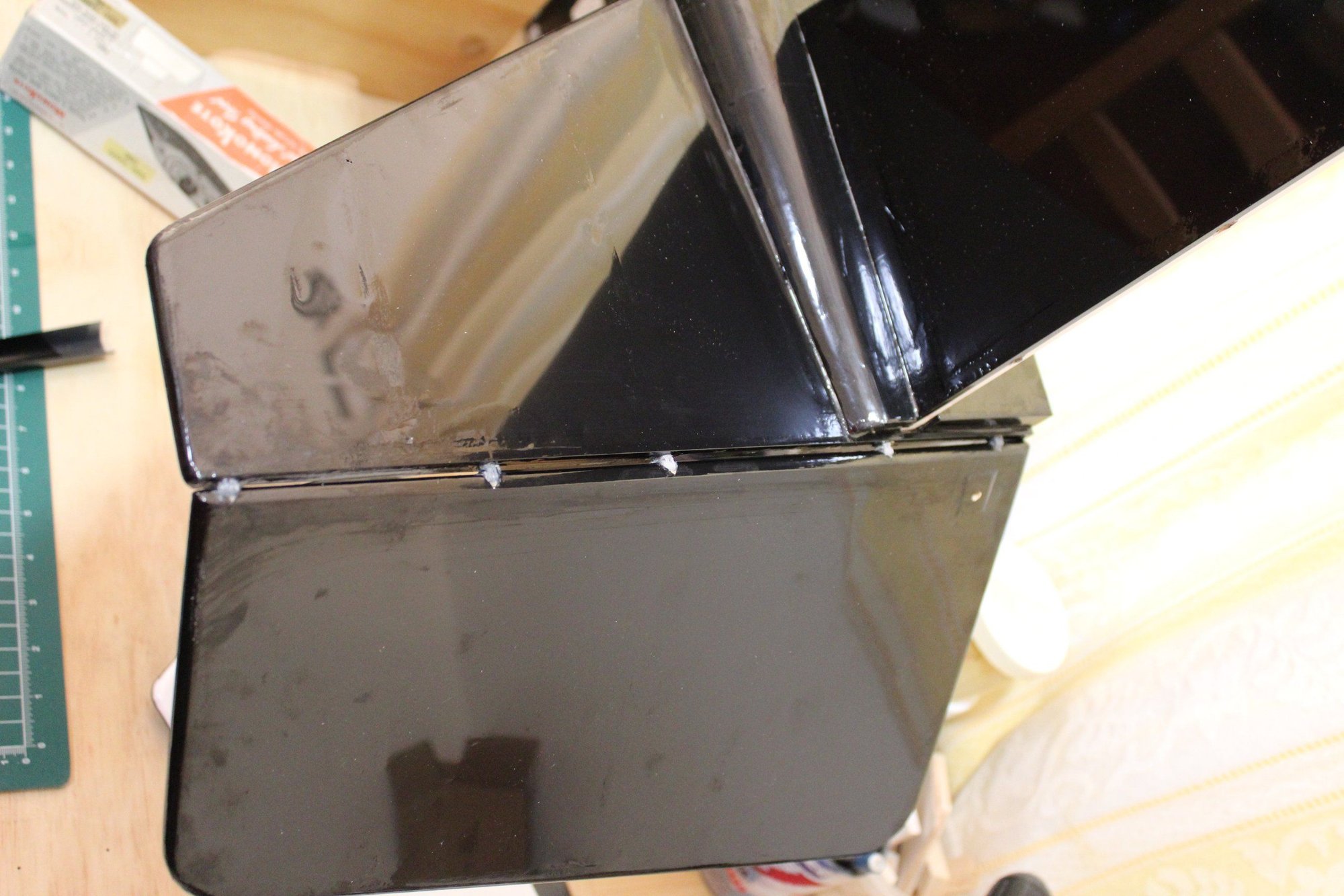
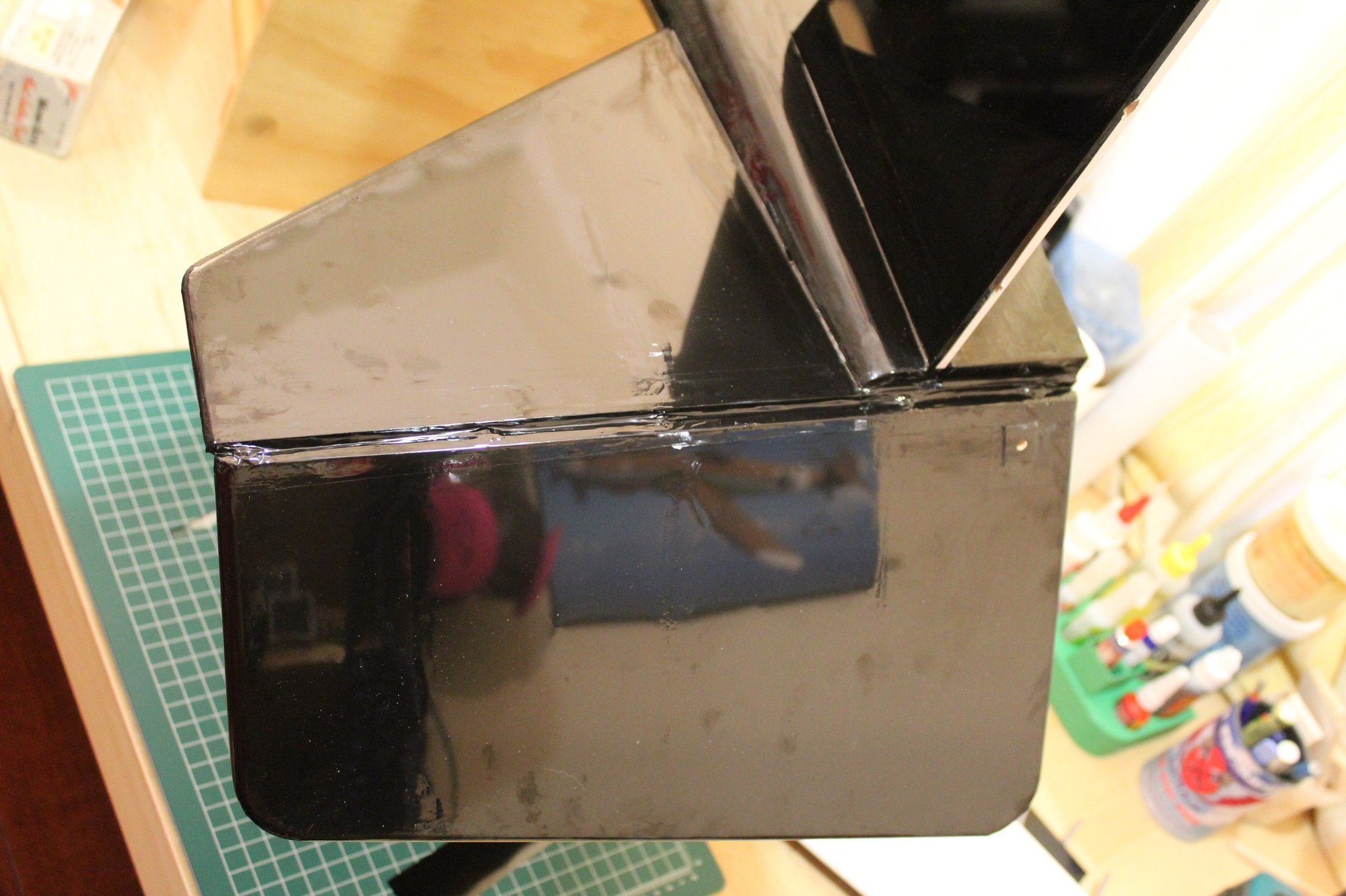
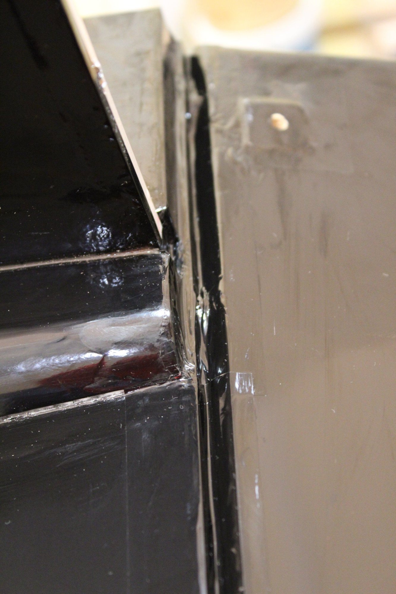
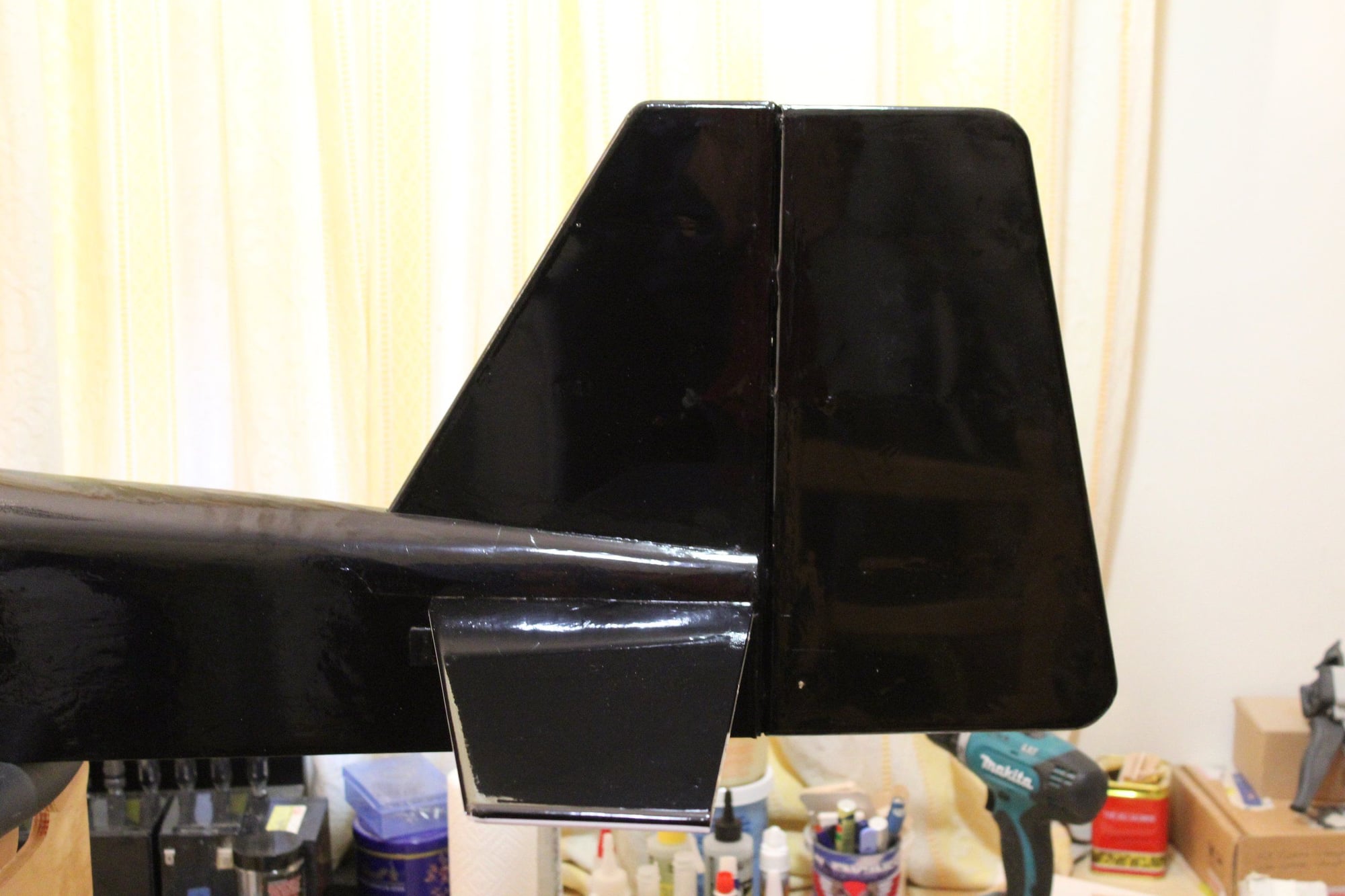
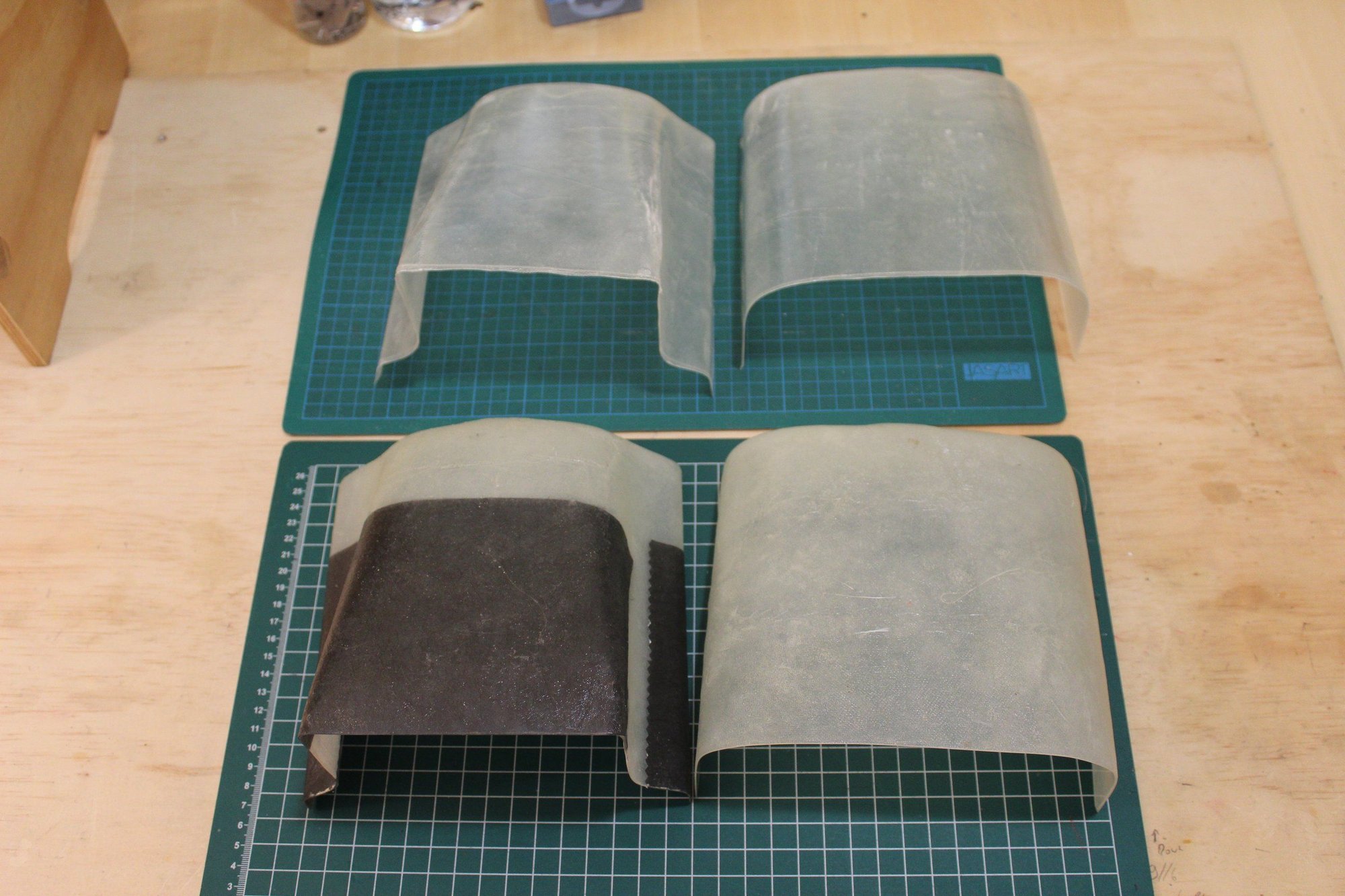
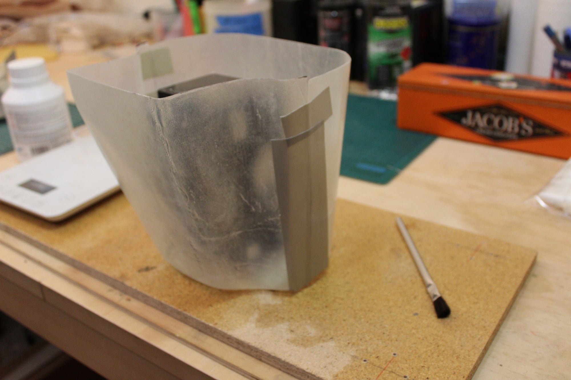
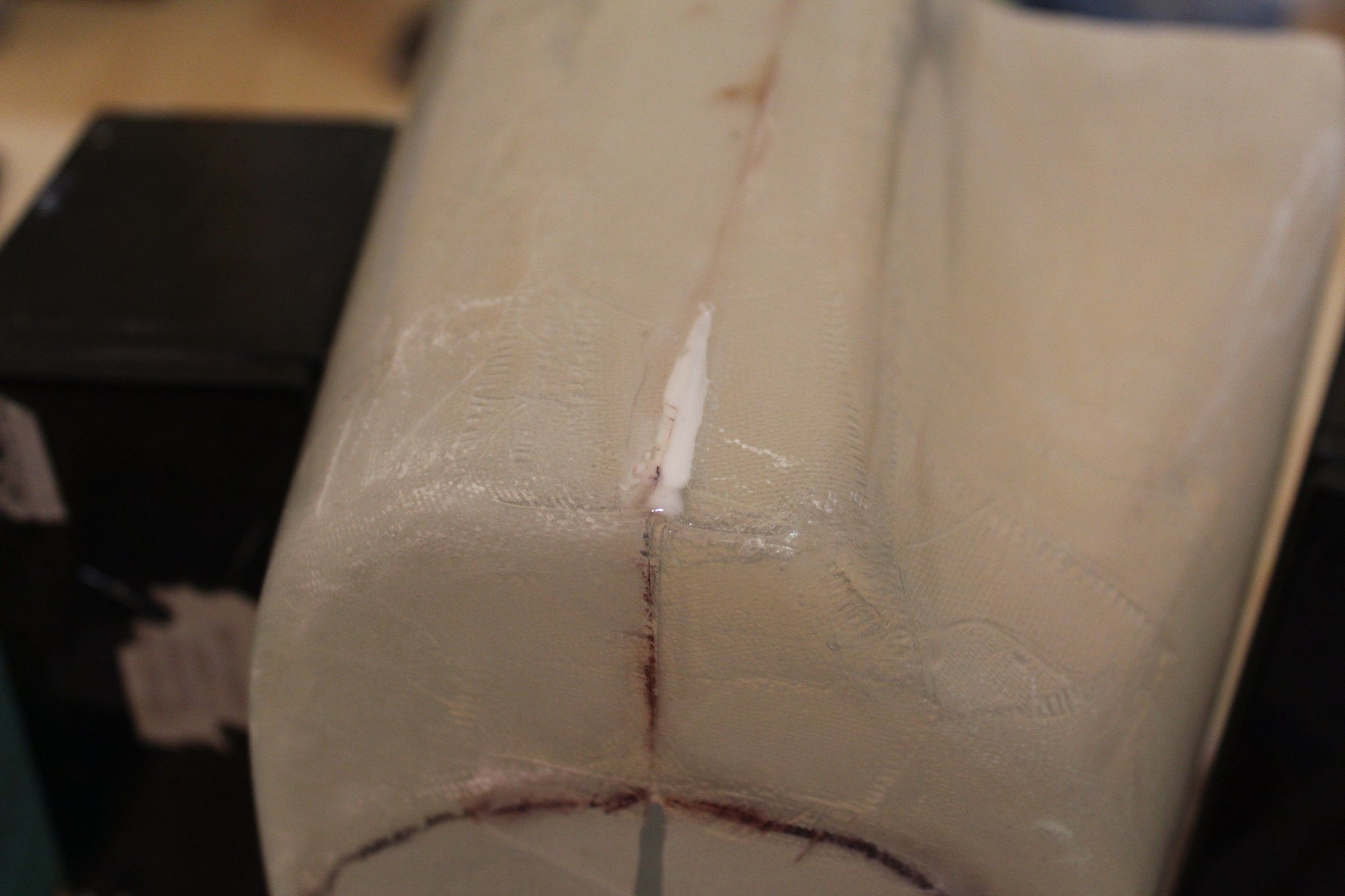
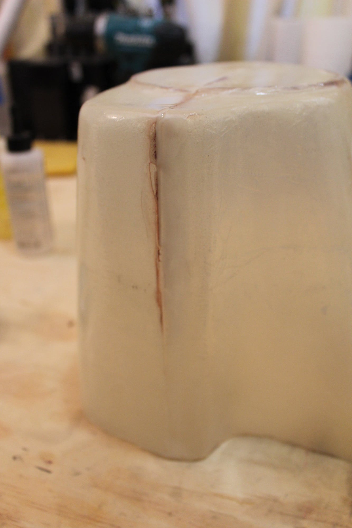
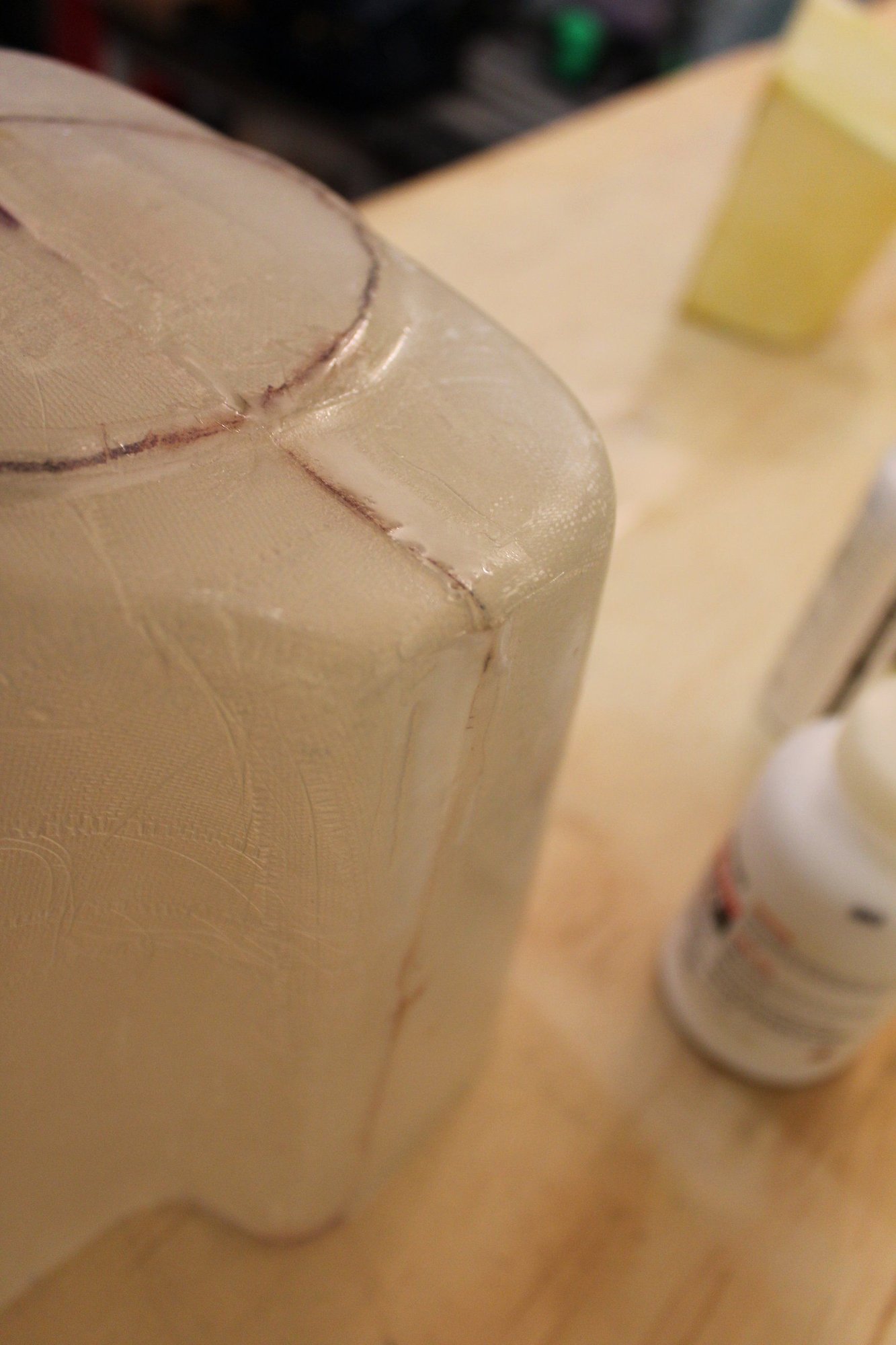
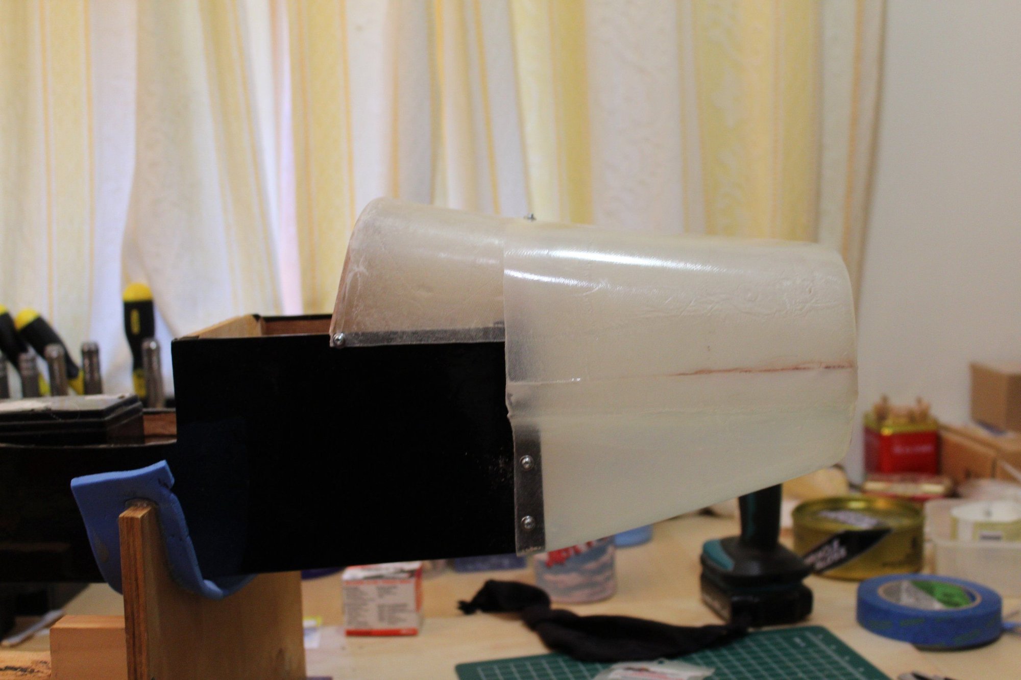
Few tasks achieved. I separated the fibreglass mould from the ABS plastic with great difficulty as it stuck at the edge 90 degree bend quite badly.
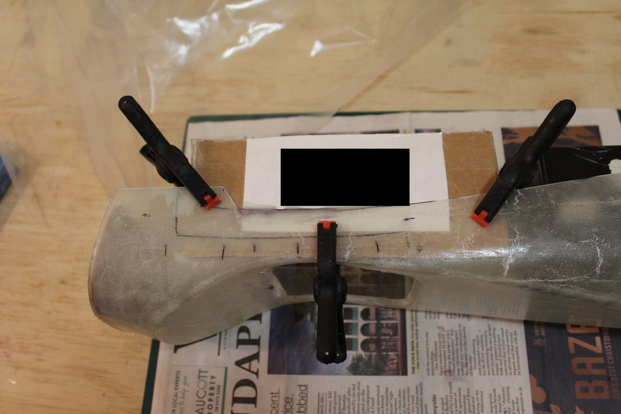
I then attended to the task of joining the top and bottom cowl parts. I taped the parts from the outside and used a battery to hold it in place on the board. I used strips of fibreglass on the seam.
Cheers,
Eran.
I then attended to the task of joining the top and bottom cowl parts. I taped the parts from the outside and used a battery to hold it in place on the board. I used strips of fibreglass on the seam.
Cheers,
Eran.
 02-28-2024, 03:18 AM
#88
Thread Starter
Join Date: Jun 2008
Location: Perth WA, AUSTRALIA
Posts: 1,208
Likes: 0
Received 12 Likes
on
12 Posts
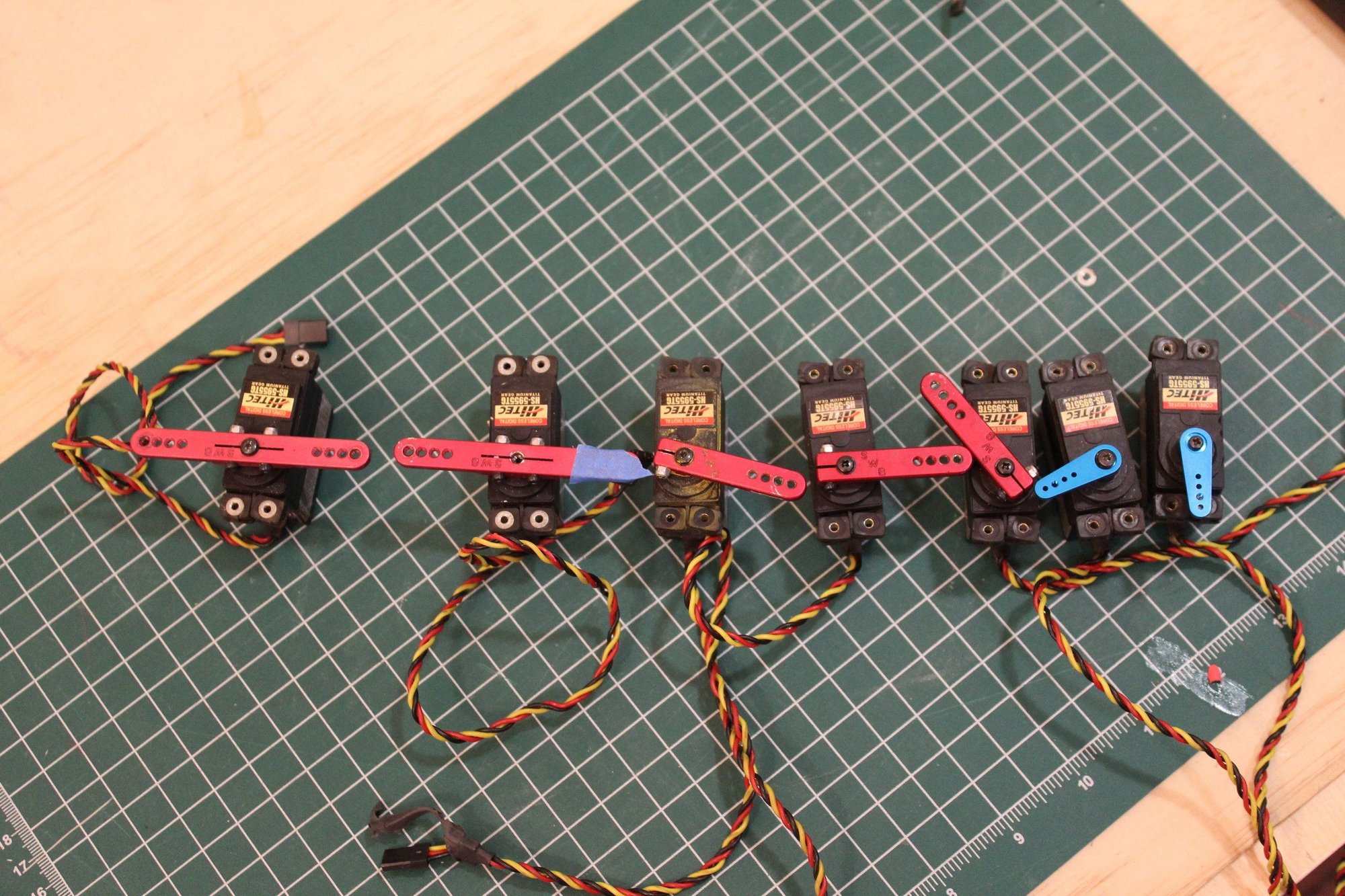
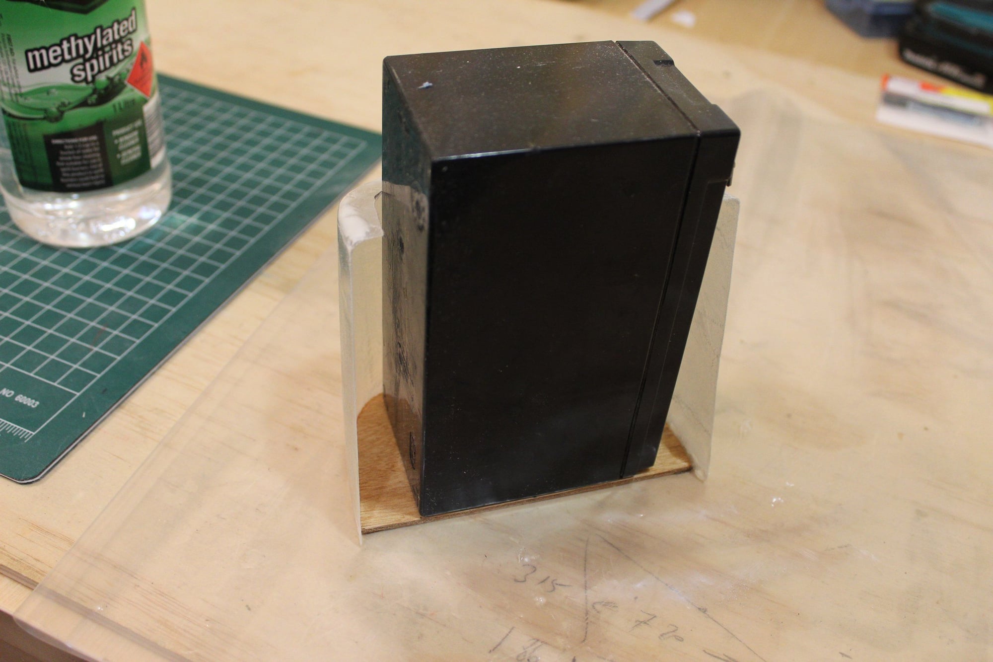
I received a bunch of Hitec HS-5655TG servos I bought second hand. I tested them all and they all work perfectly ready for installation in the Stinger.
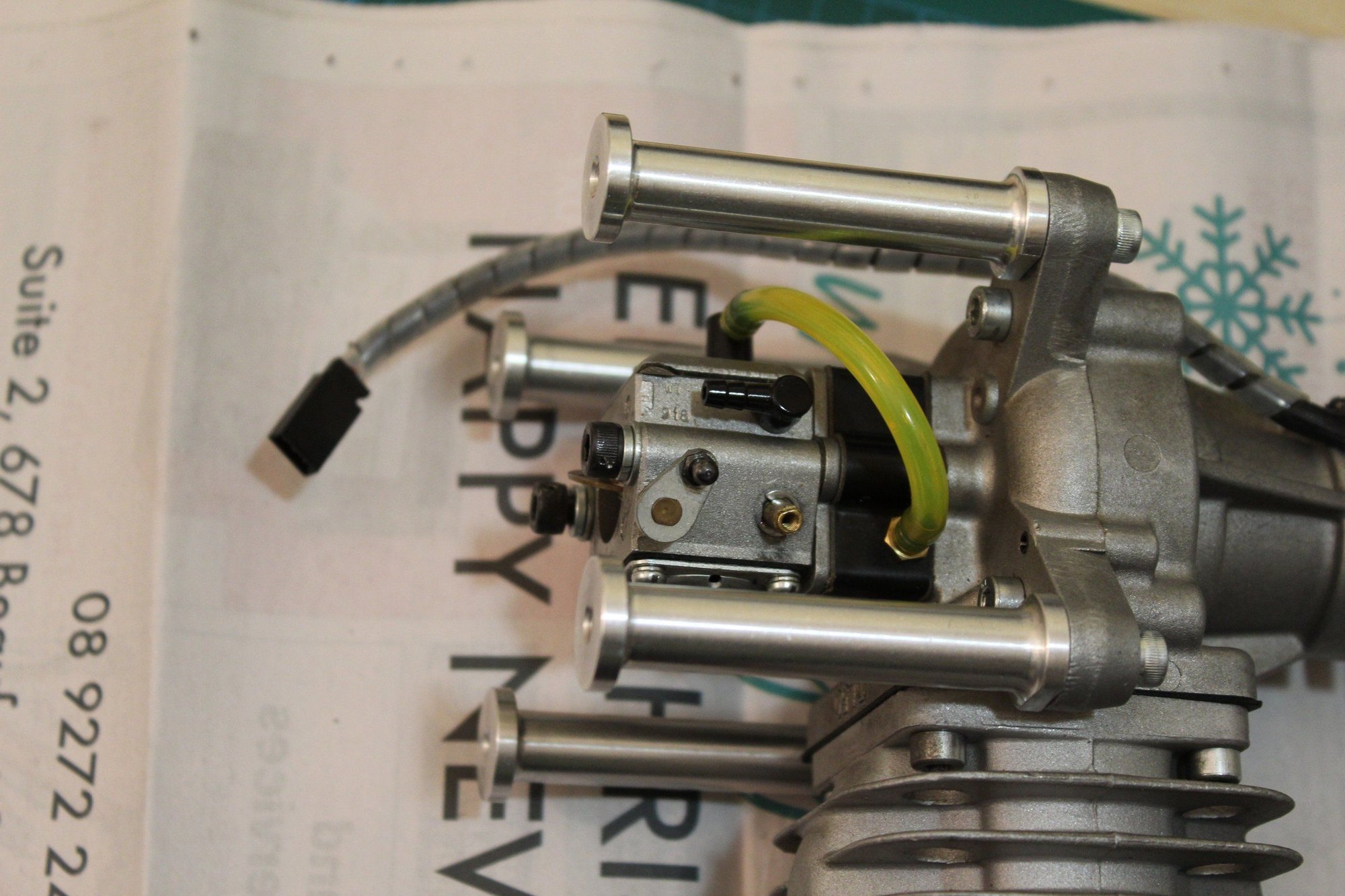
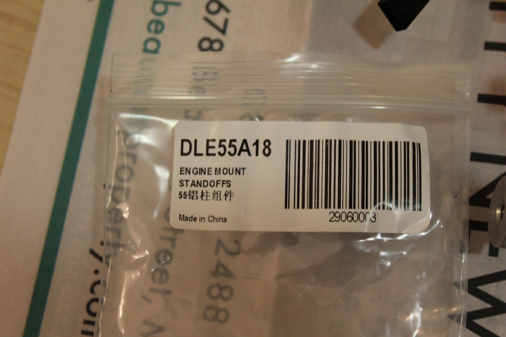
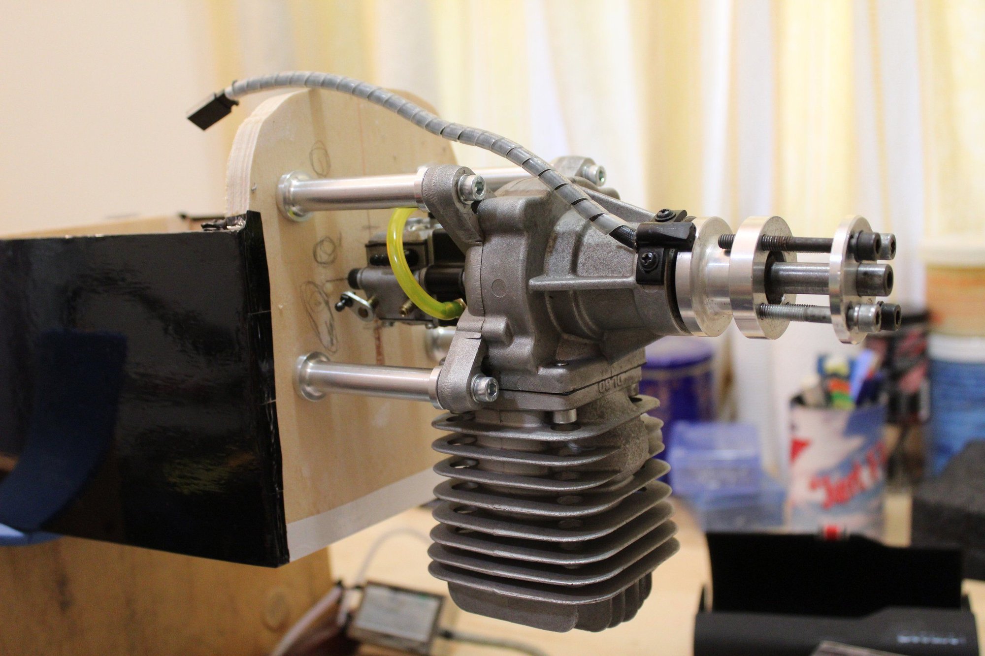
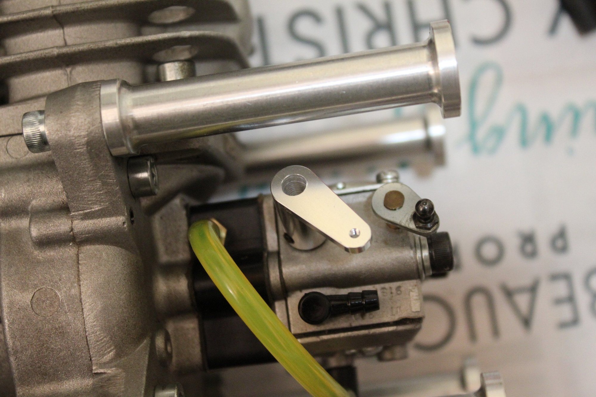
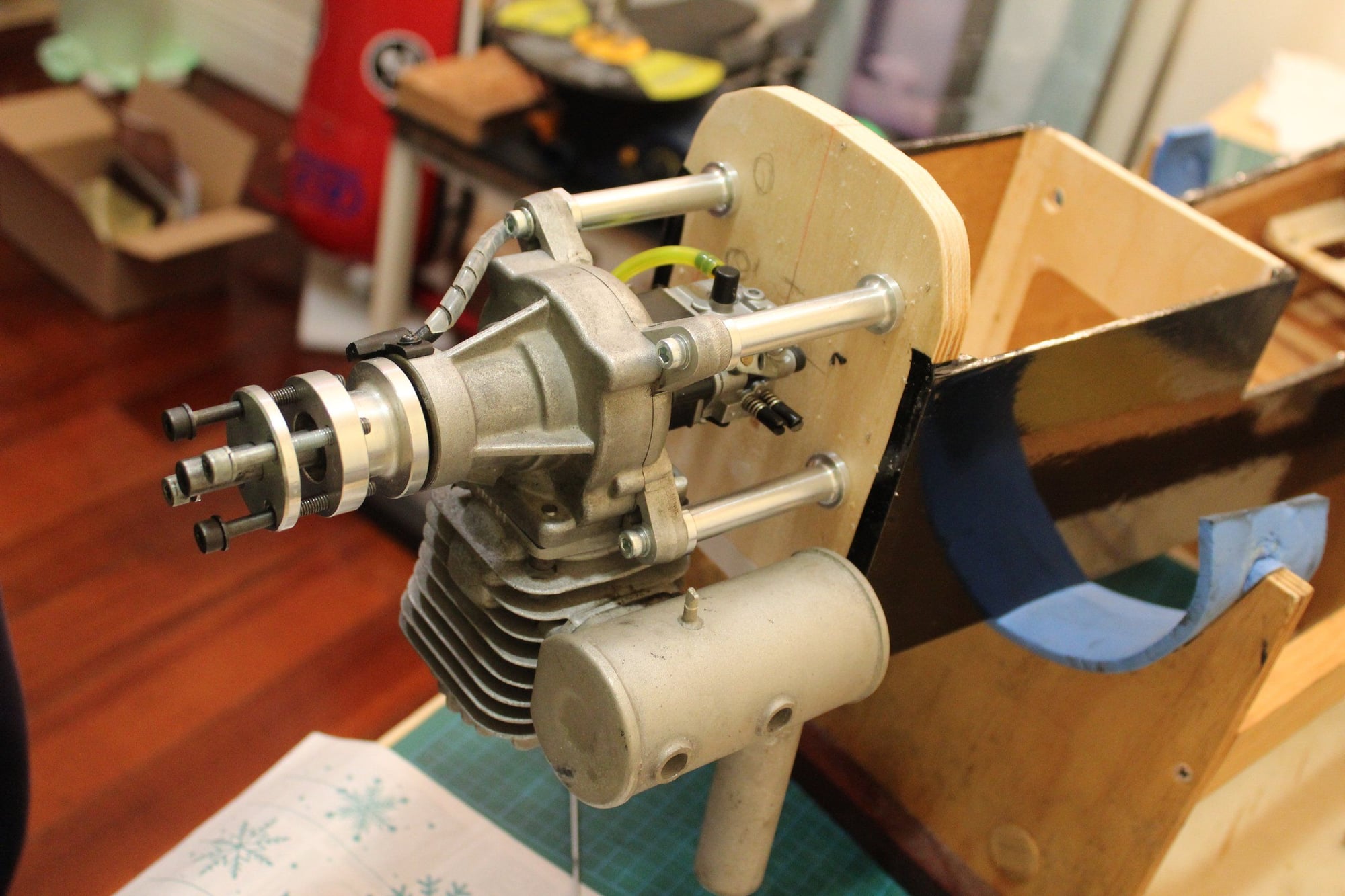
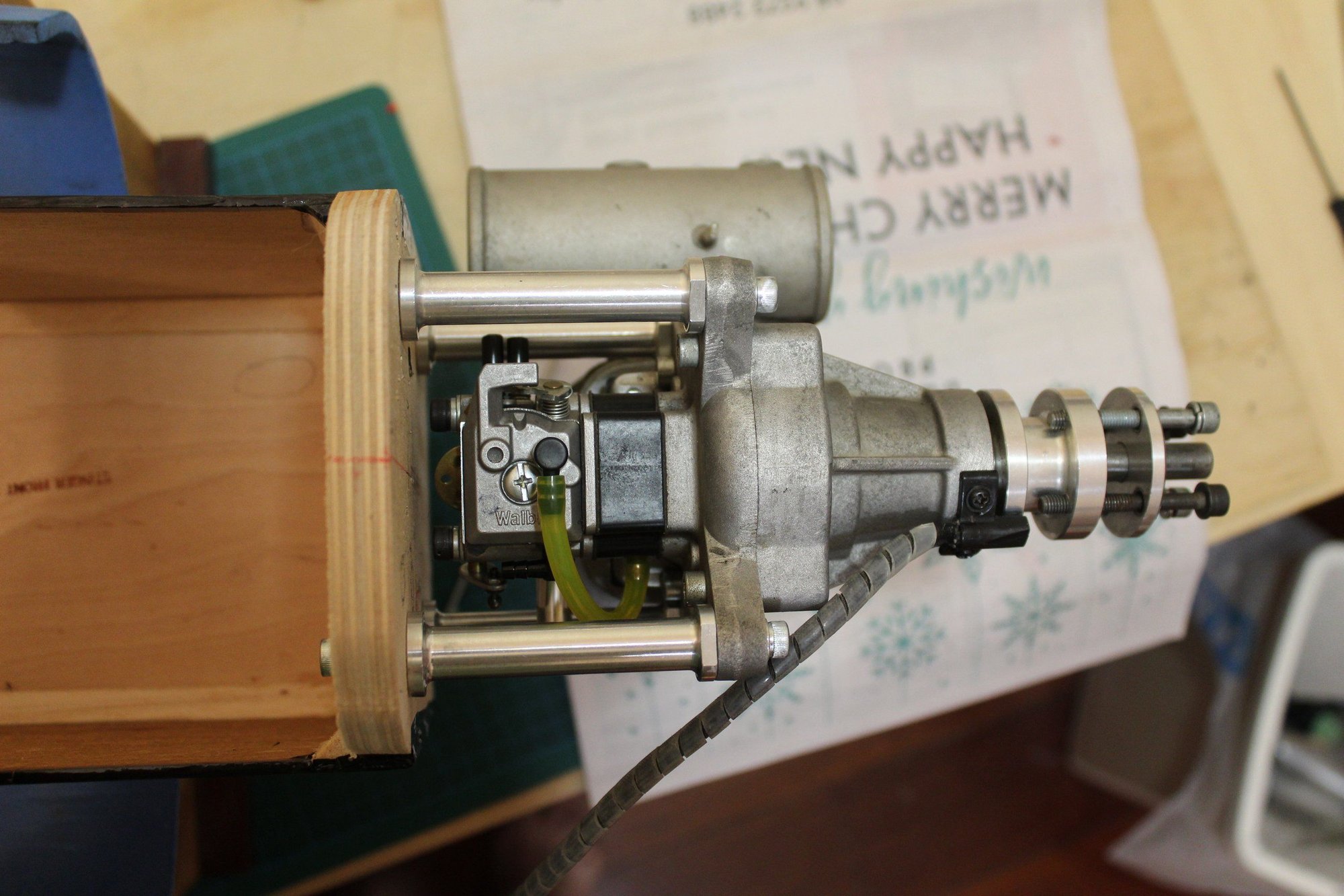
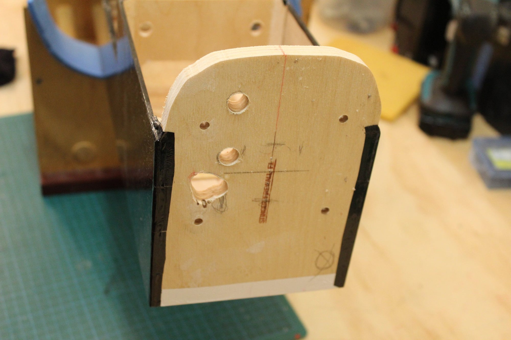
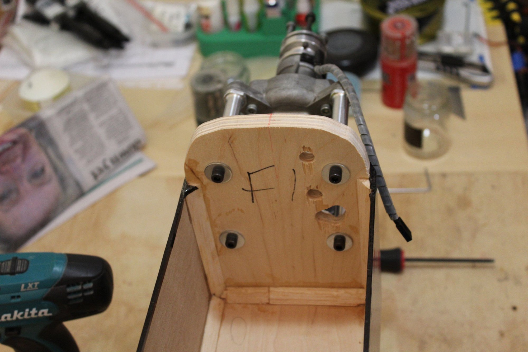
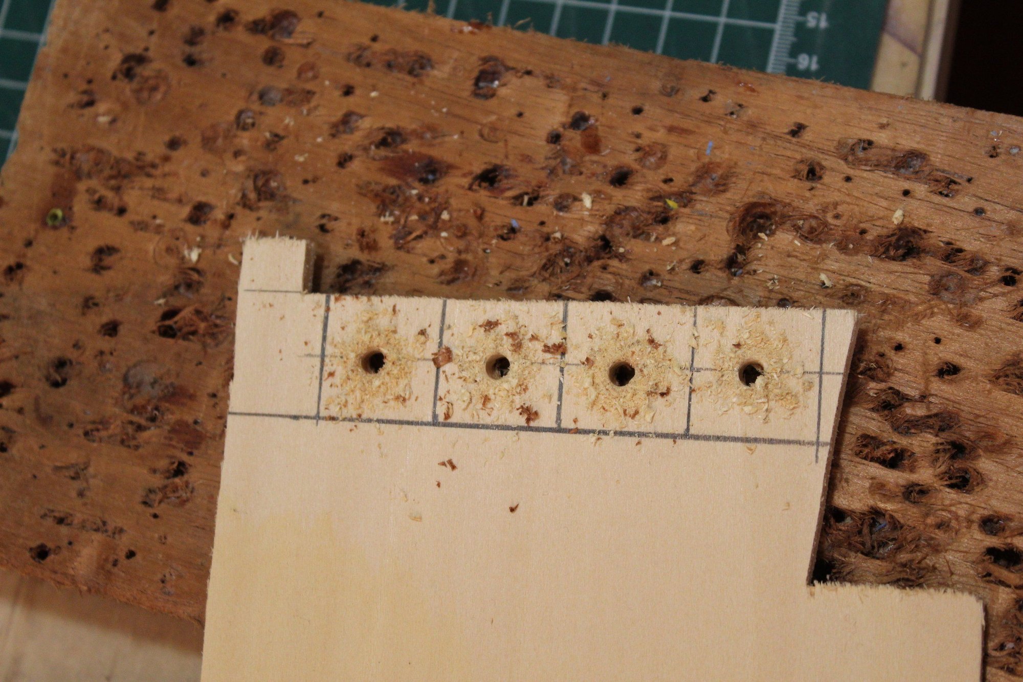
I fitted the DL-50 engine with DLE 55 standoffs and a large throttle arm I had in my drawer. I then test fitted the engine to the firewall and marked the relevant holes I need to drill and drilled them out.

Cheers,
Eran.
I fitted the DL-50 engine with DLE 55 standoffs and a large throttle arm I had in my drawer. I then test fitted the engine to the firewall and marked the relevant holes I need to drill and drilled them out.
Cheers,
Eran.
02-29-2024, 01:03 AM
#89
Thread Starter
Join Date: Jun 2008
Location: Perth WA, AUSTRALIA
Posts: 1,208
Likes: 0
Received 12 Likes
on
12 Posts
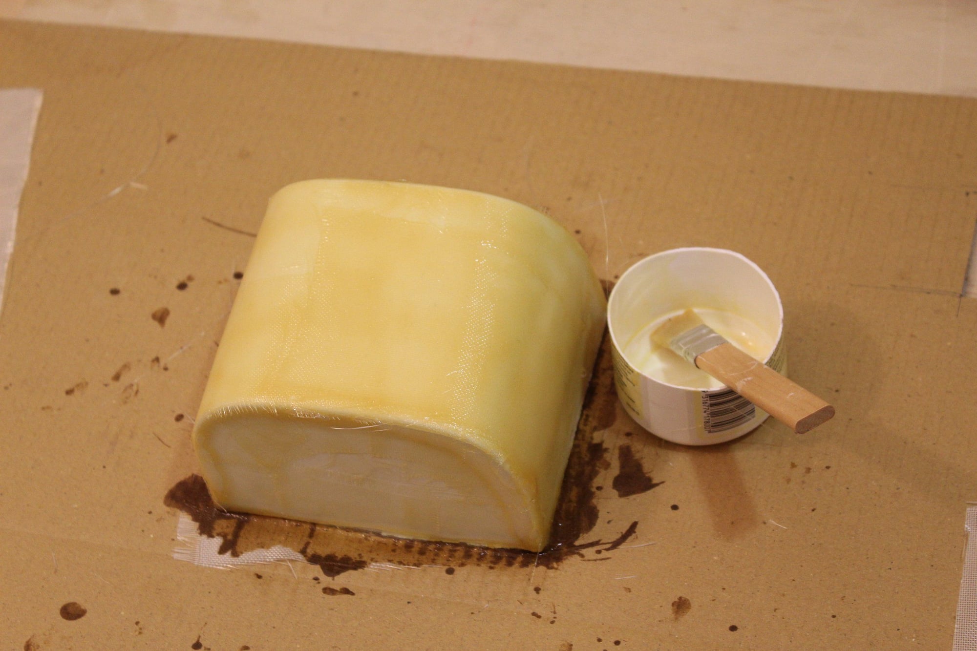
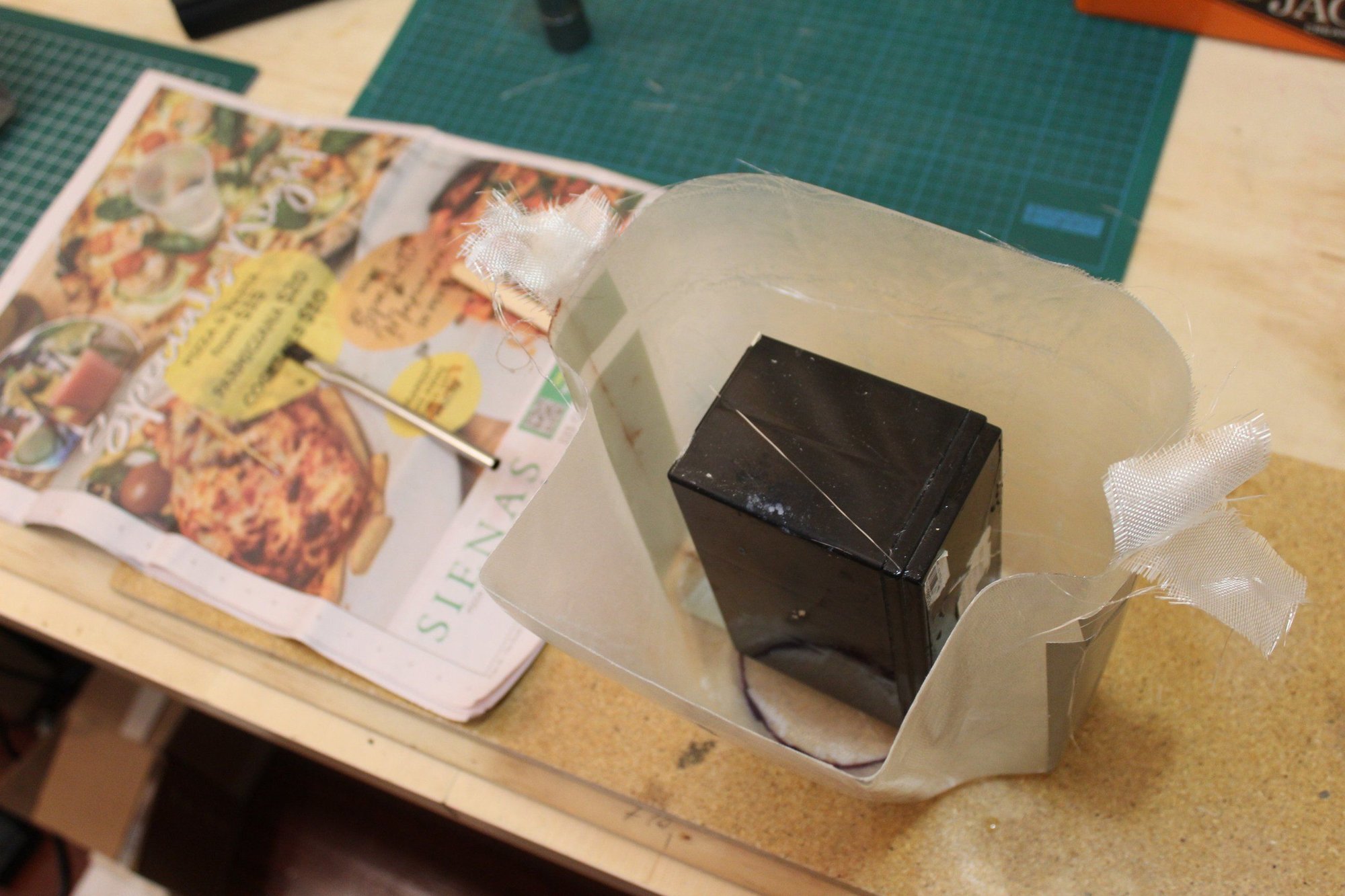
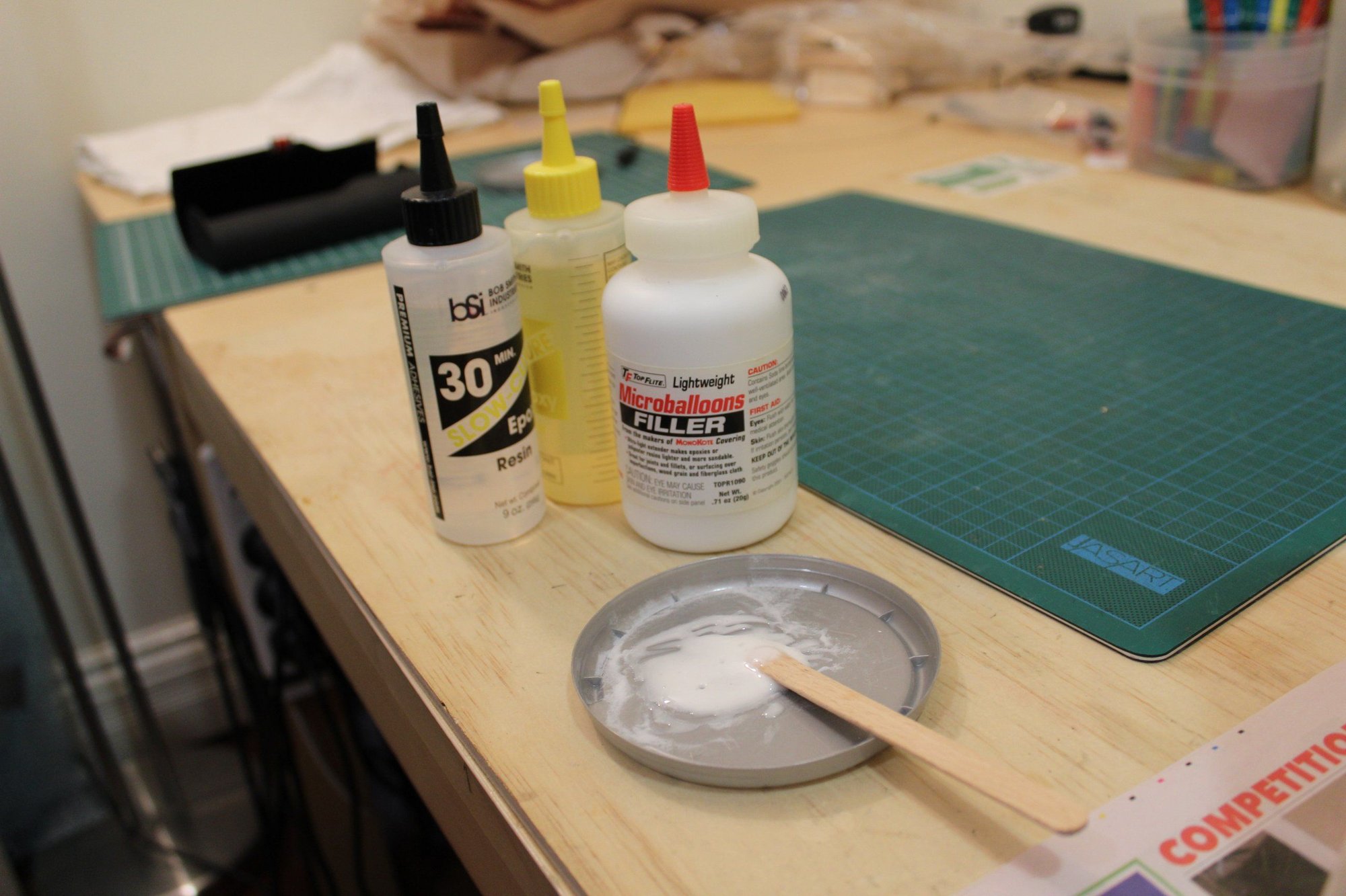
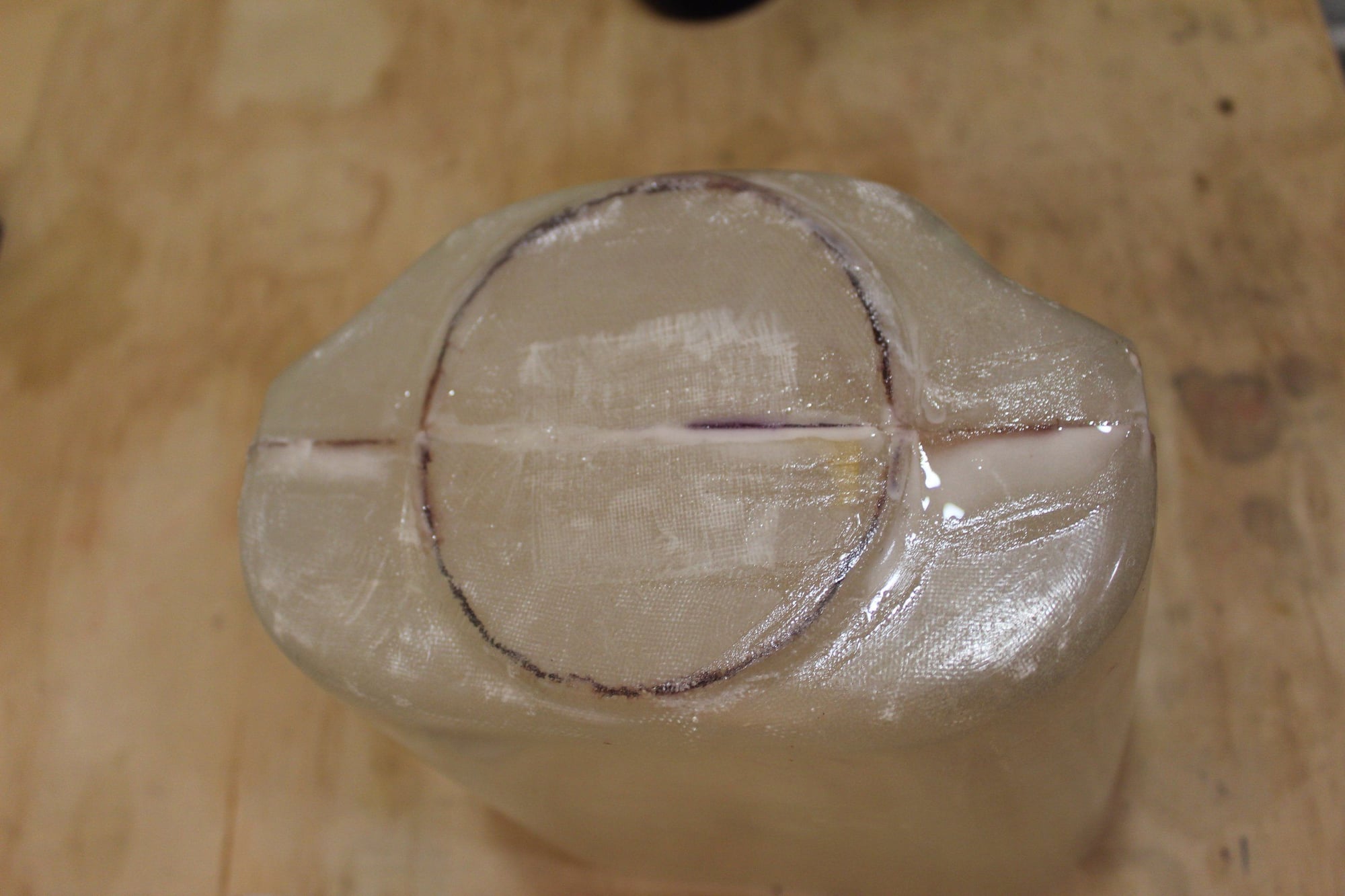
I waxed the mould and laid out the fibreglass for the tank cover part. I then used the excess Epoxy resin to fuel proof the fuel tank area and the firewall.
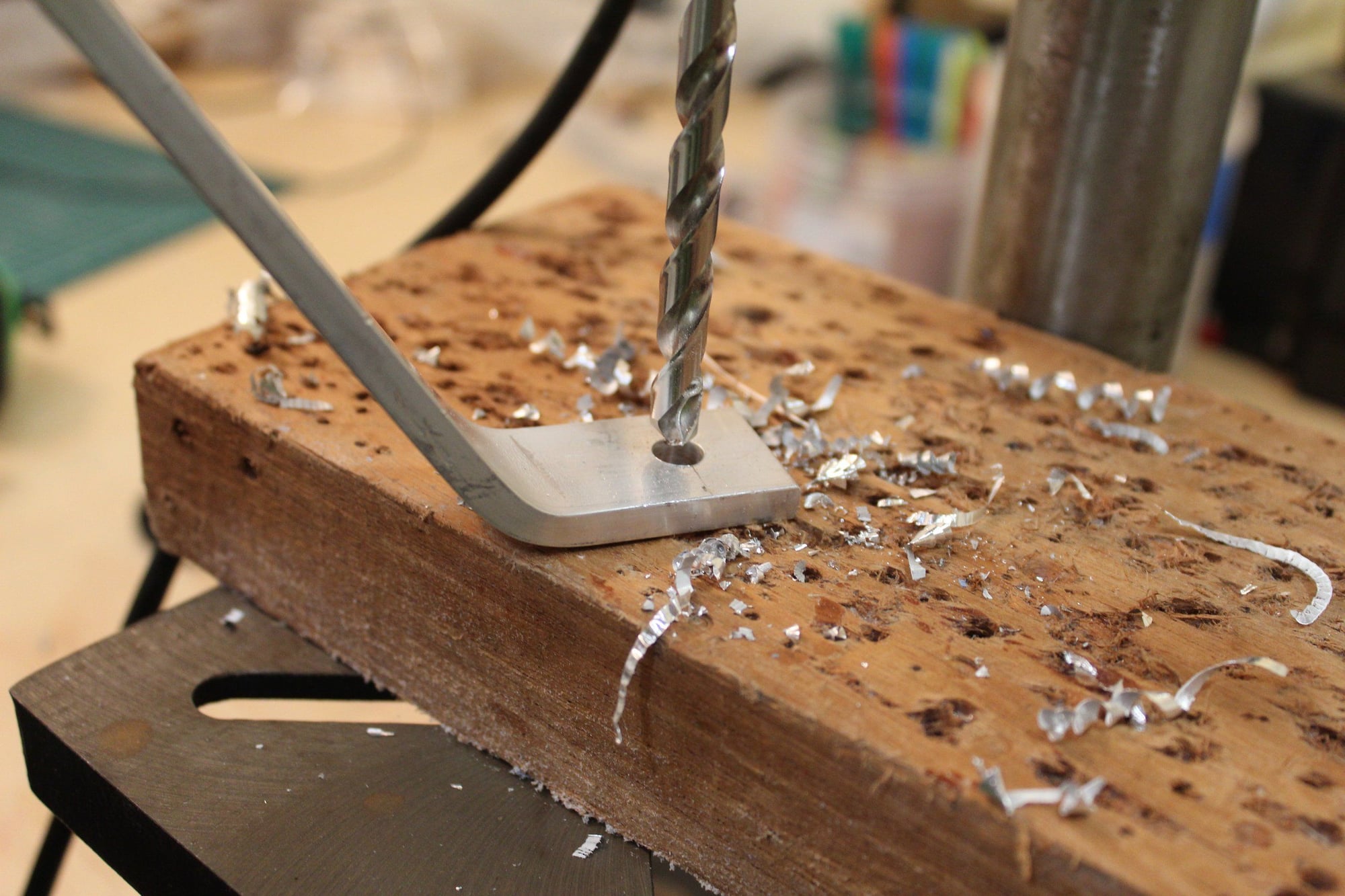
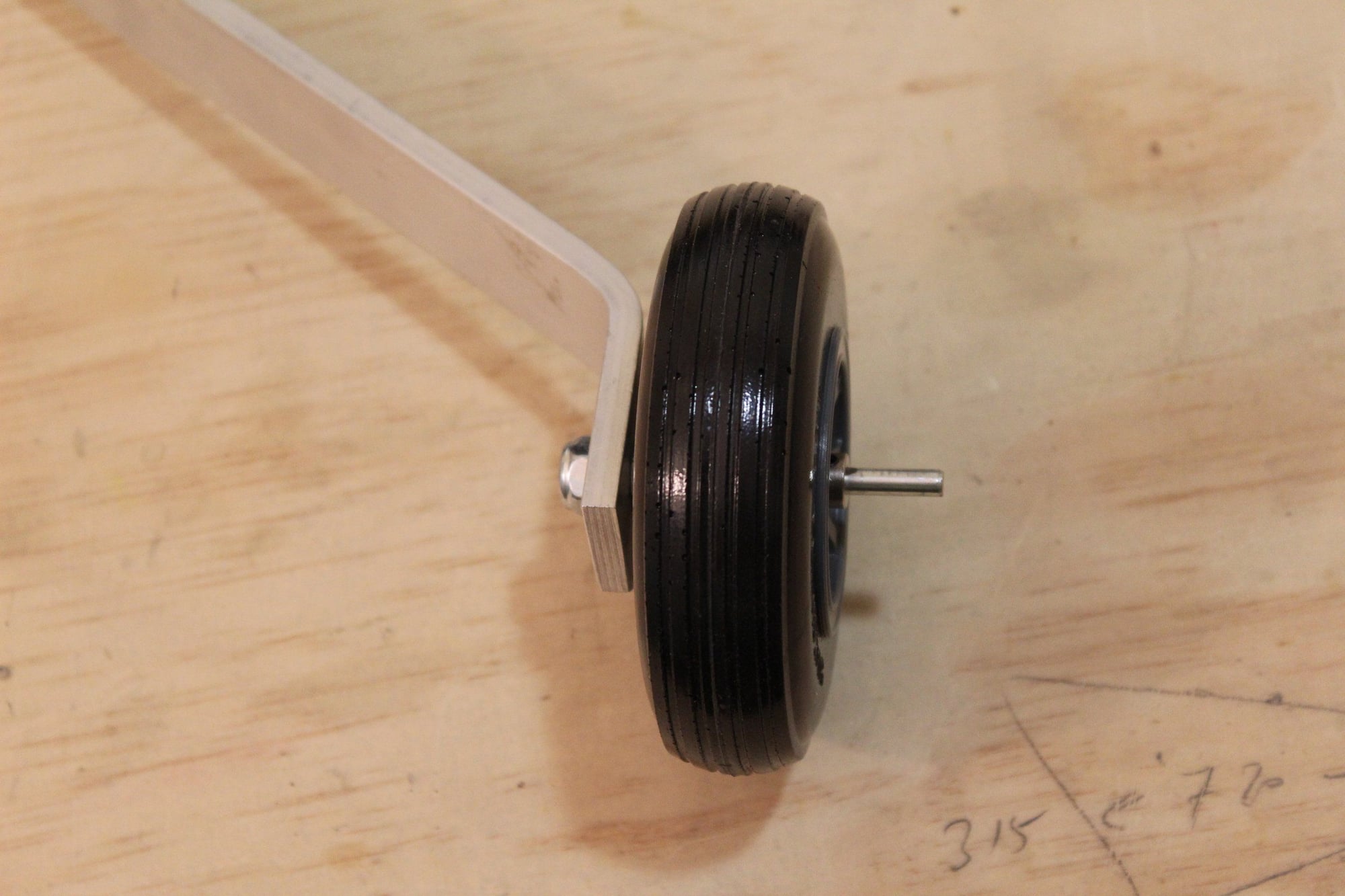
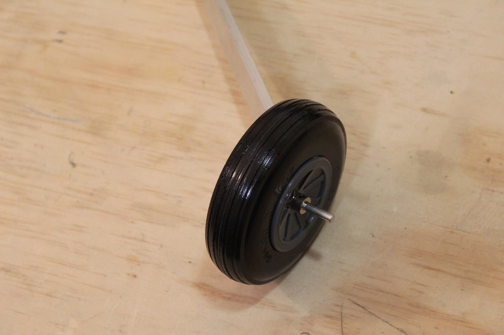
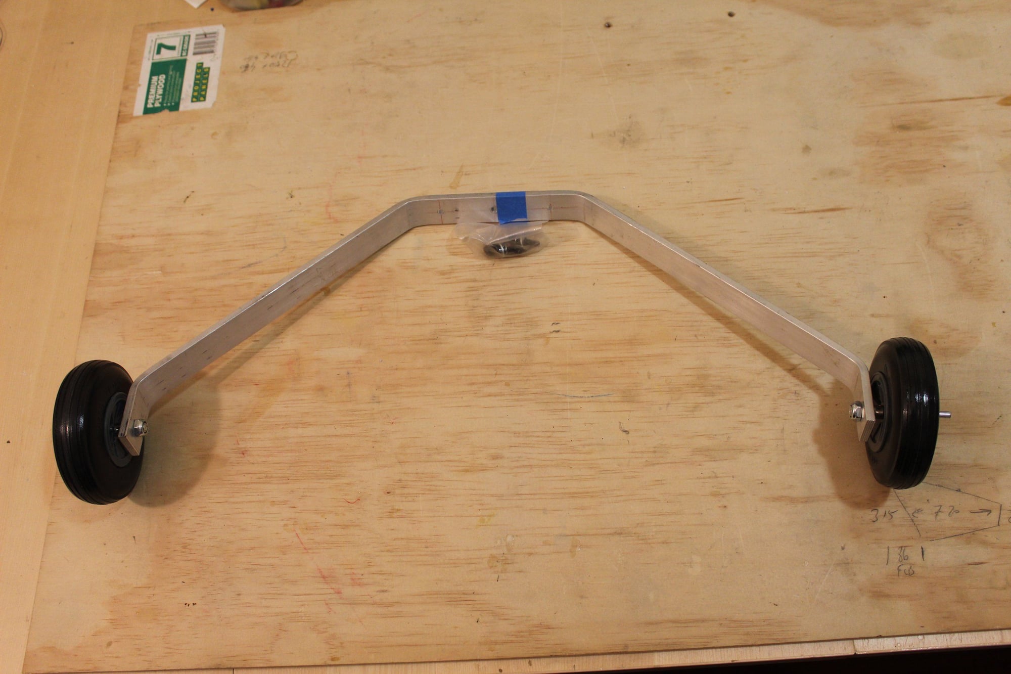
I also drilled and assembled the landing gear.
Cheers,
Eran
I also drilled and assembled the landing gear.
Cheers,
Eran
03-02-2024, 04:13 AM
#90
Thread Starter
Join Date: Jun 2008
Location: Perth WA, AUSTRALIA
Posts: 1,208
Likes: 0
Received 12 Likes
on
12 Posts
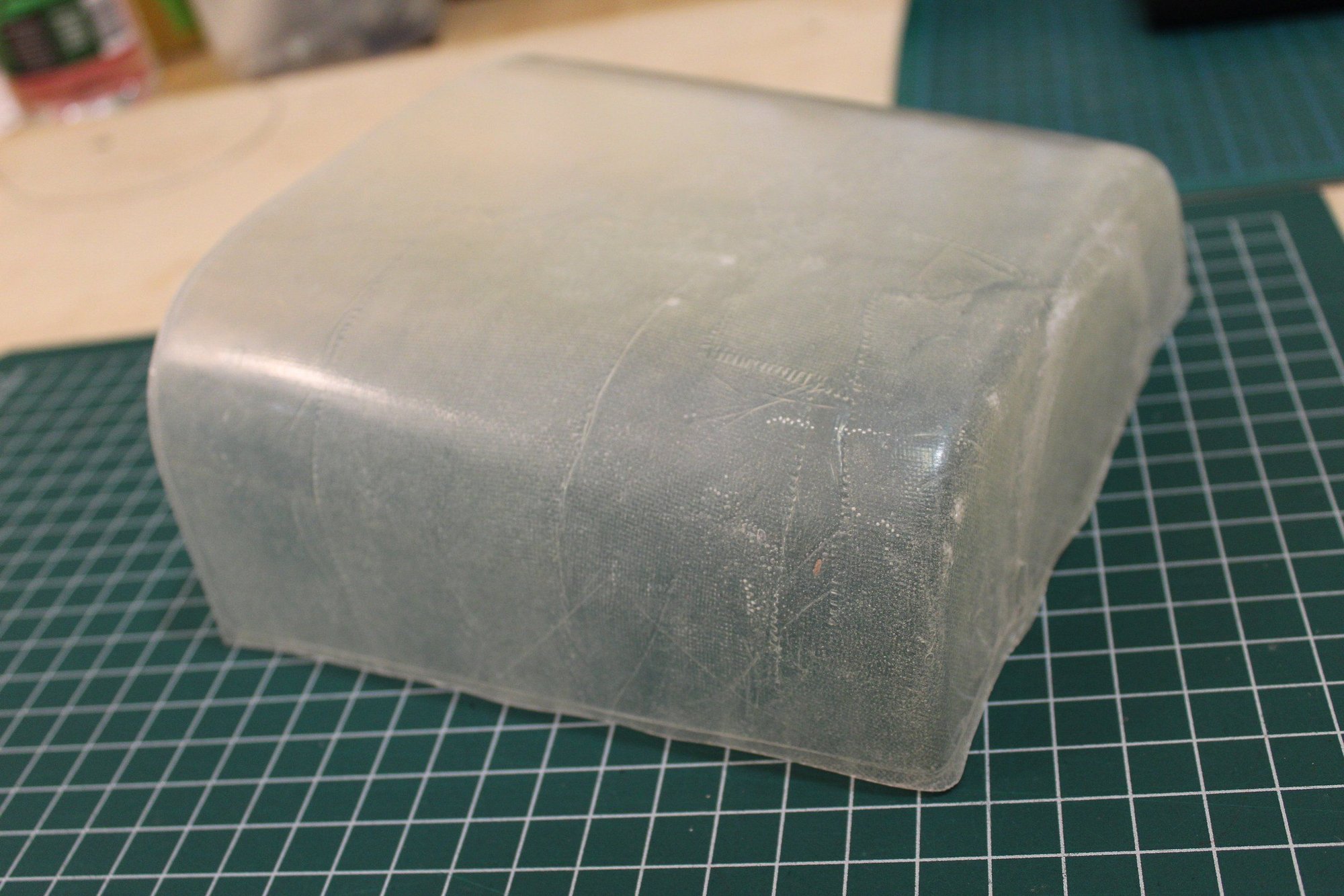
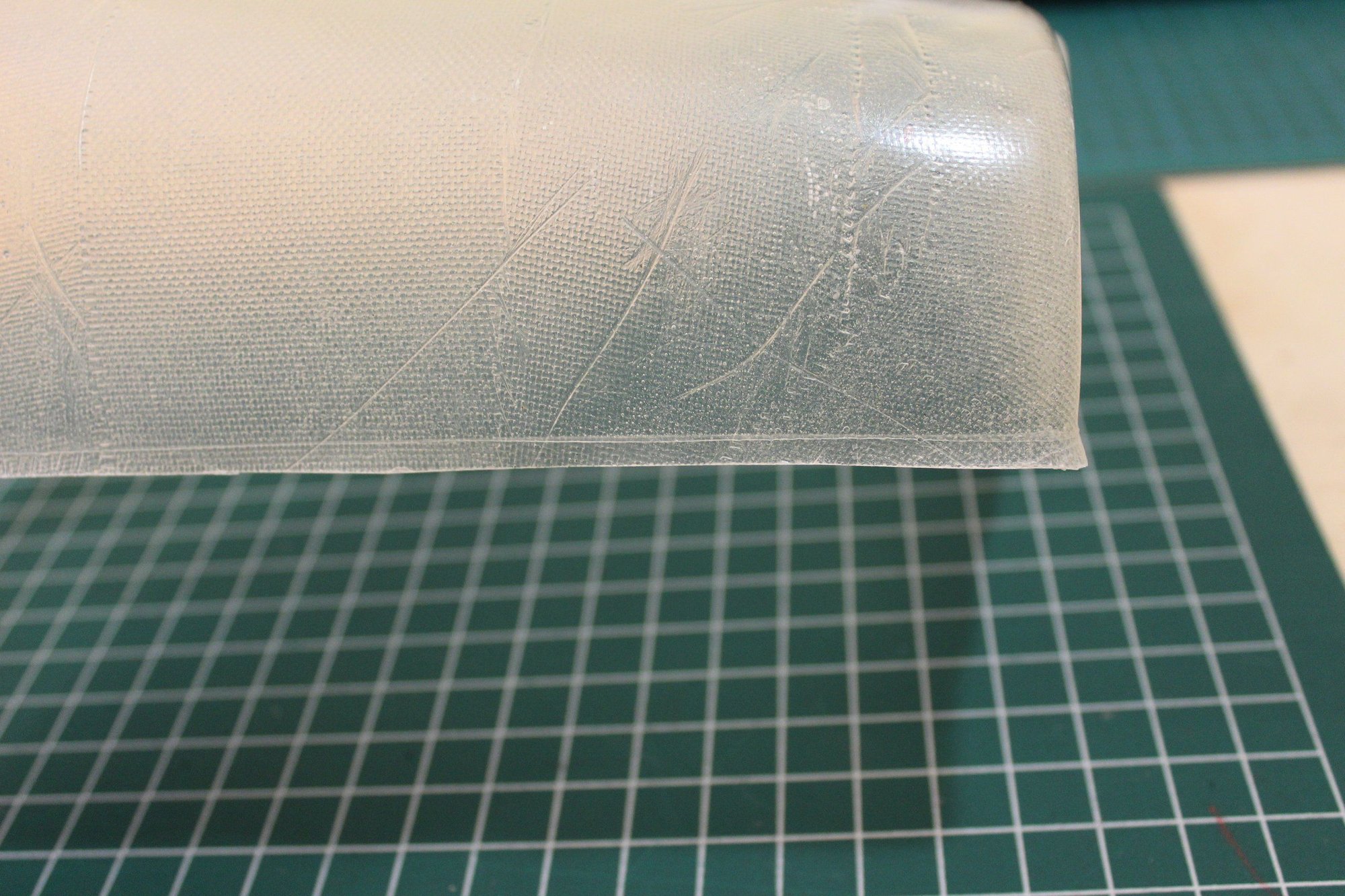
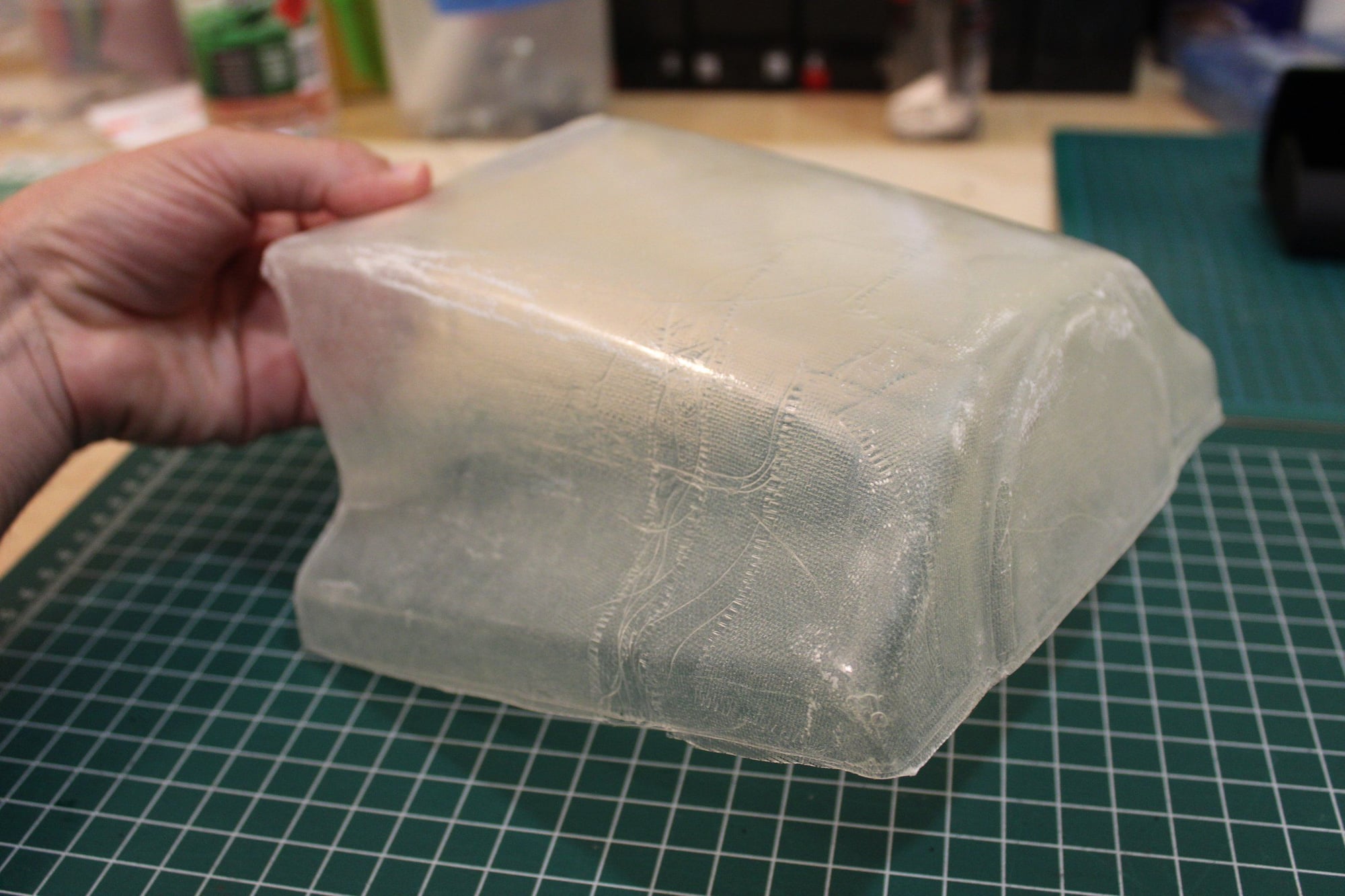
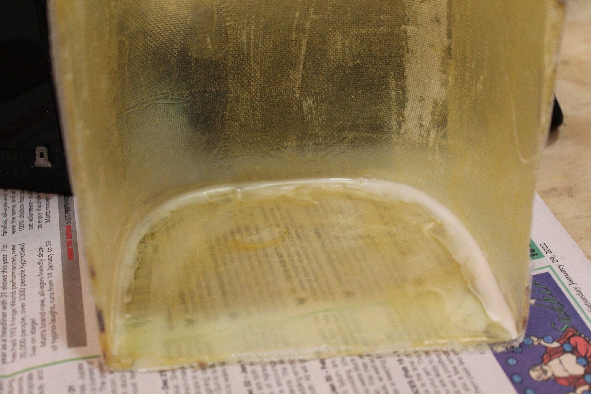
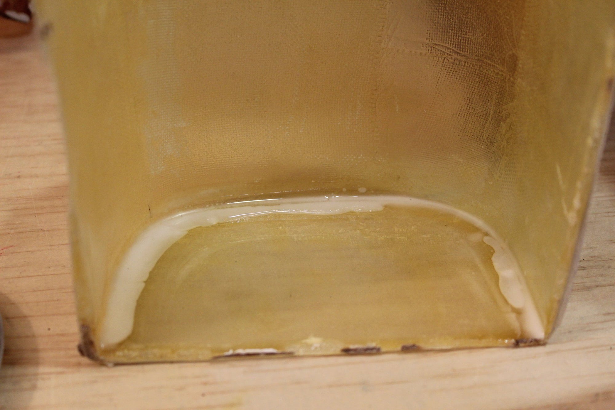
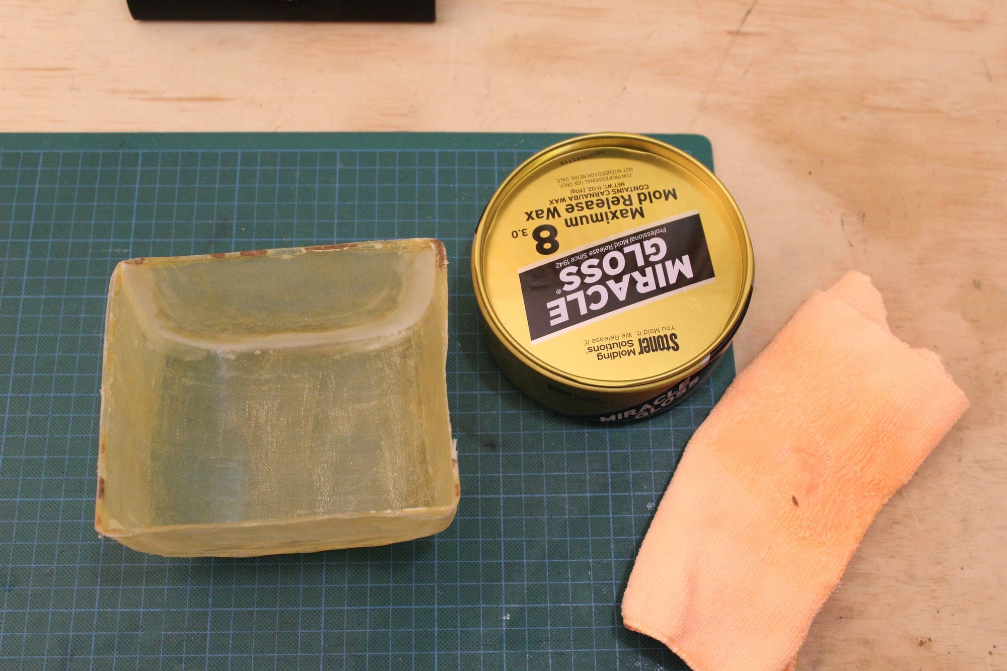
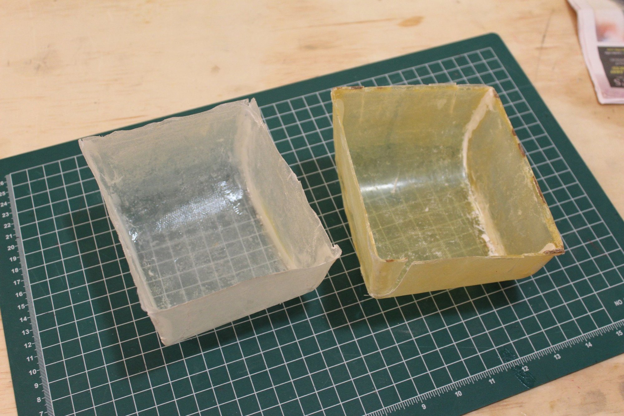
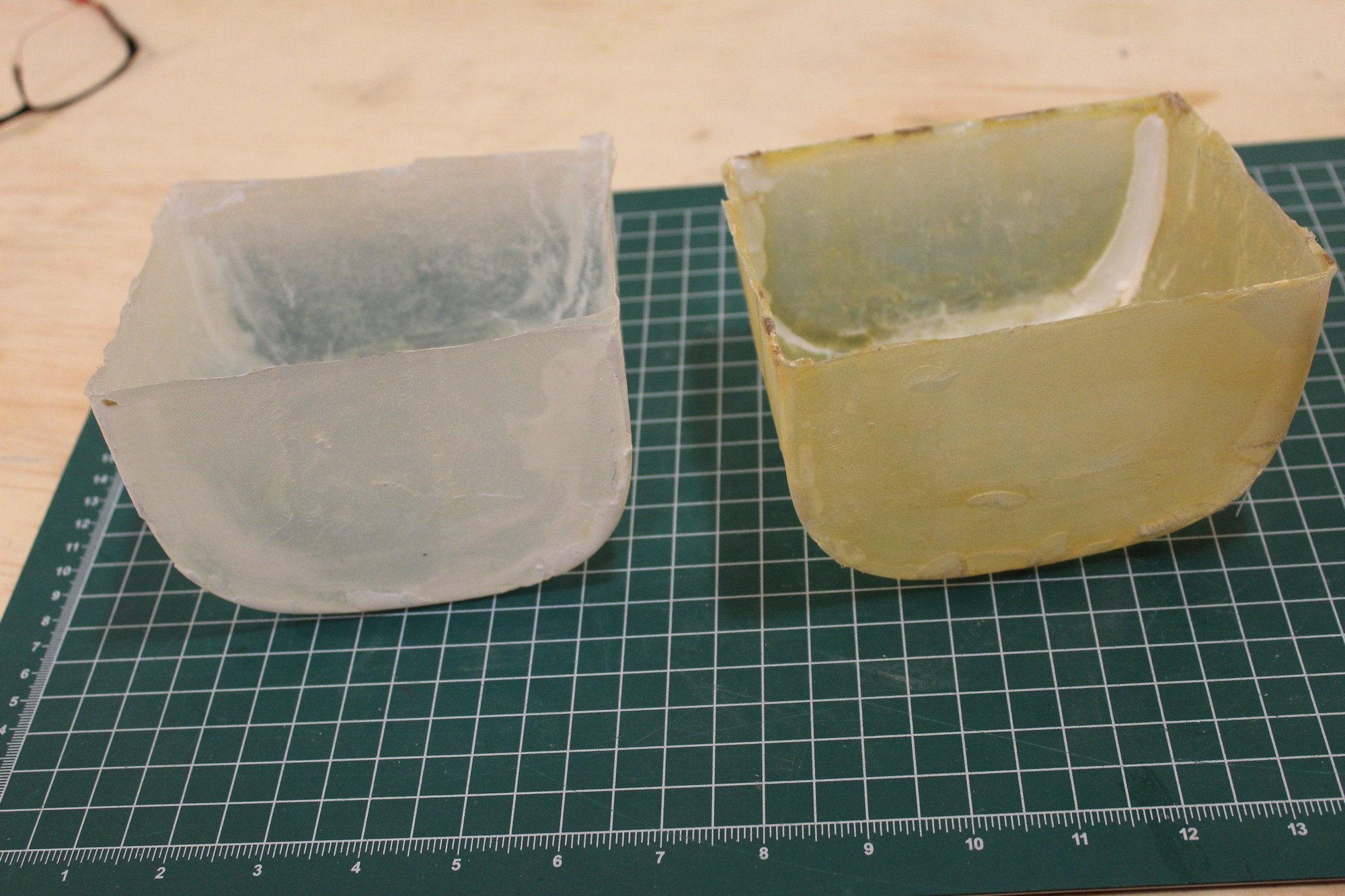
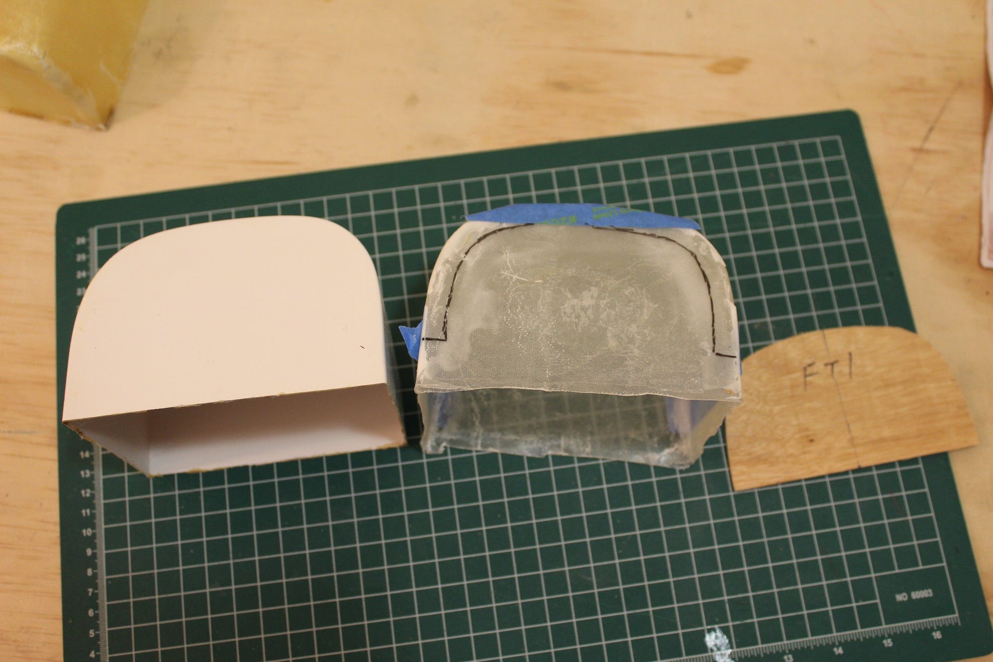
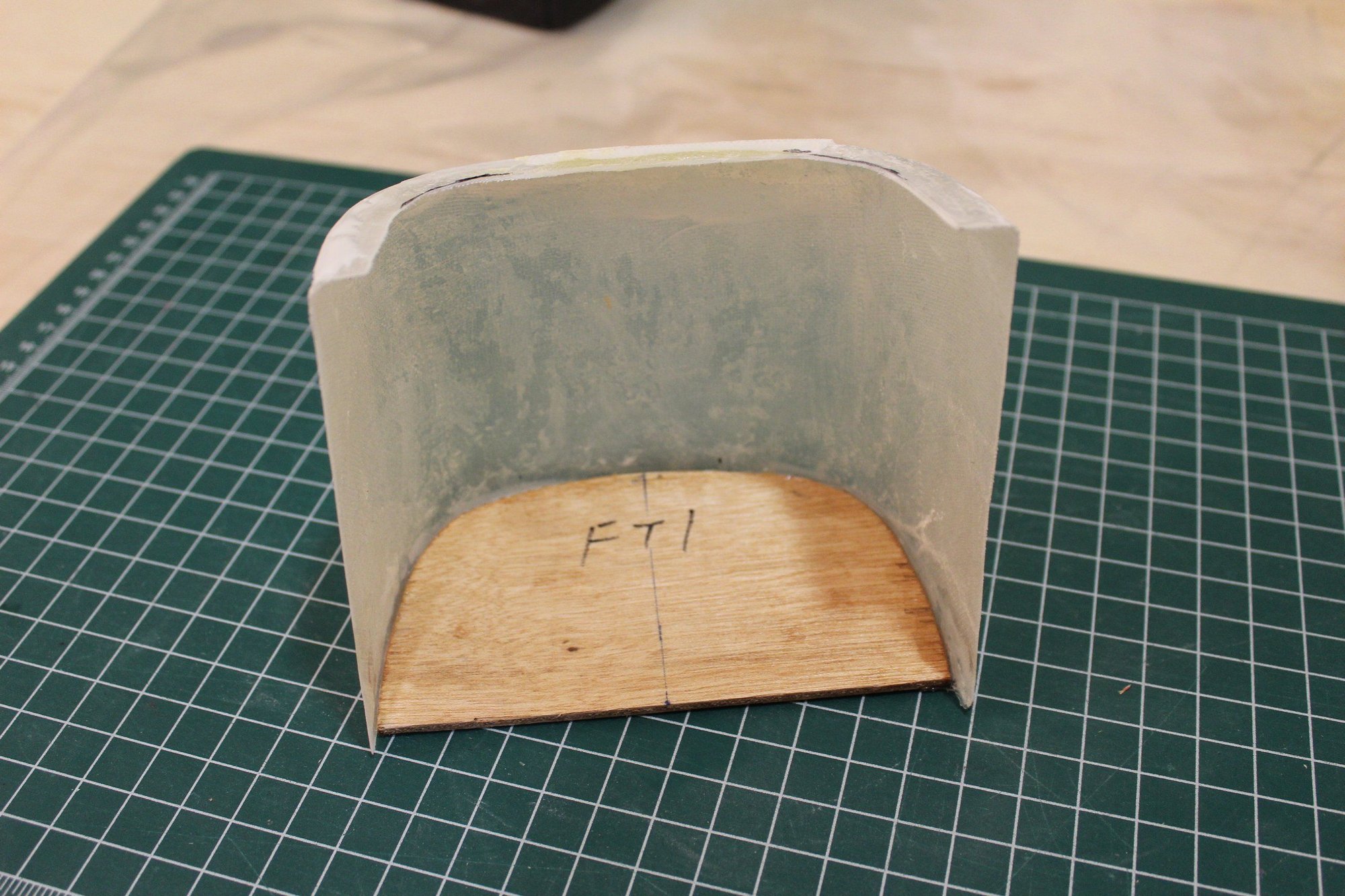
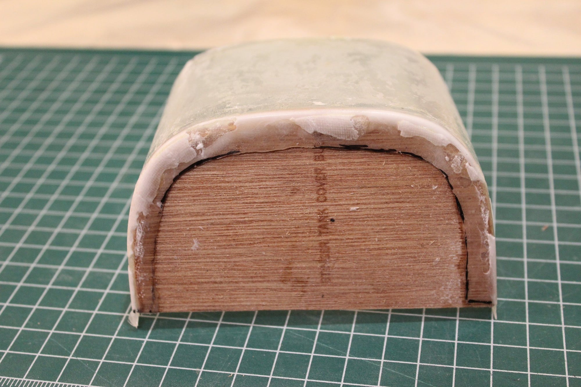
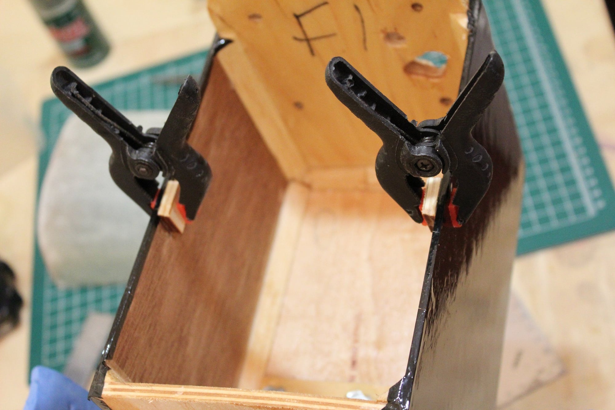
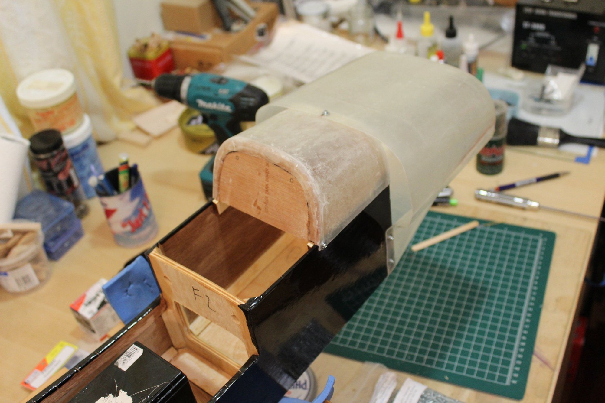
I had to ruin the mould to be able to extract the tank cover out. Even after all the preparation with the wax (5 applications) the part stuck to the mould.
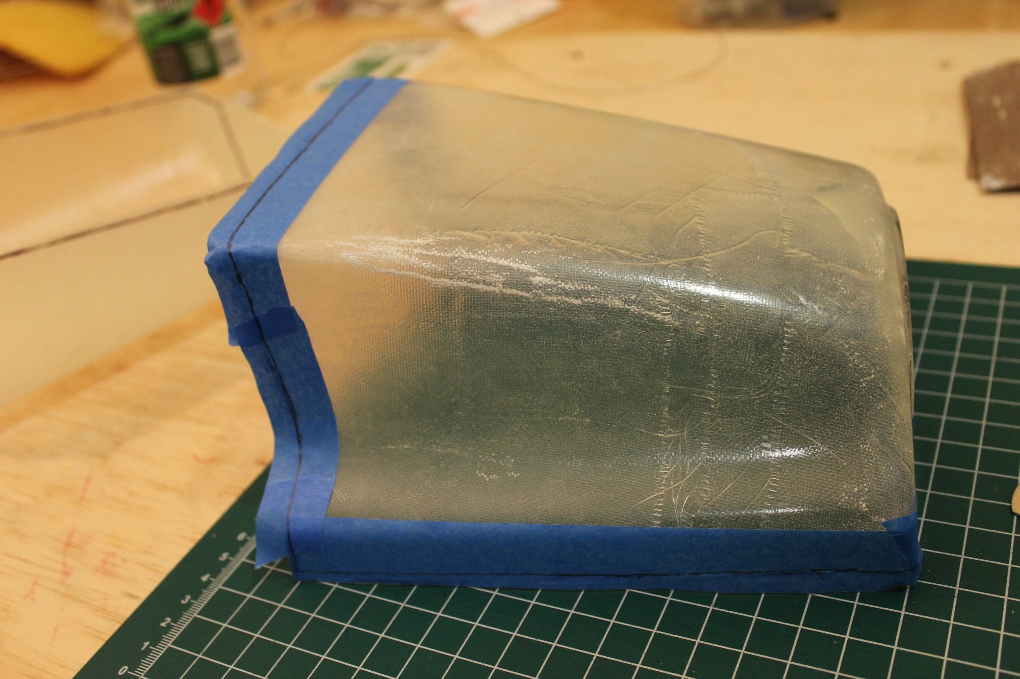
Once out, I trimmed the tank cover to shape and glued former FT1 to it.
Cheers,
Eran
Once out, I trimmed the tank cover to shape and glued former FT1 to it.
Cheers,
Eran
03-05-2024, 05:21 PM
#91
Thread Starter
Join Date: Jun 2008
Location: Perth WA, AUSTRALIA
Posts: 1,208
Likes: 0
Received 12 Likes
on
12 Posts
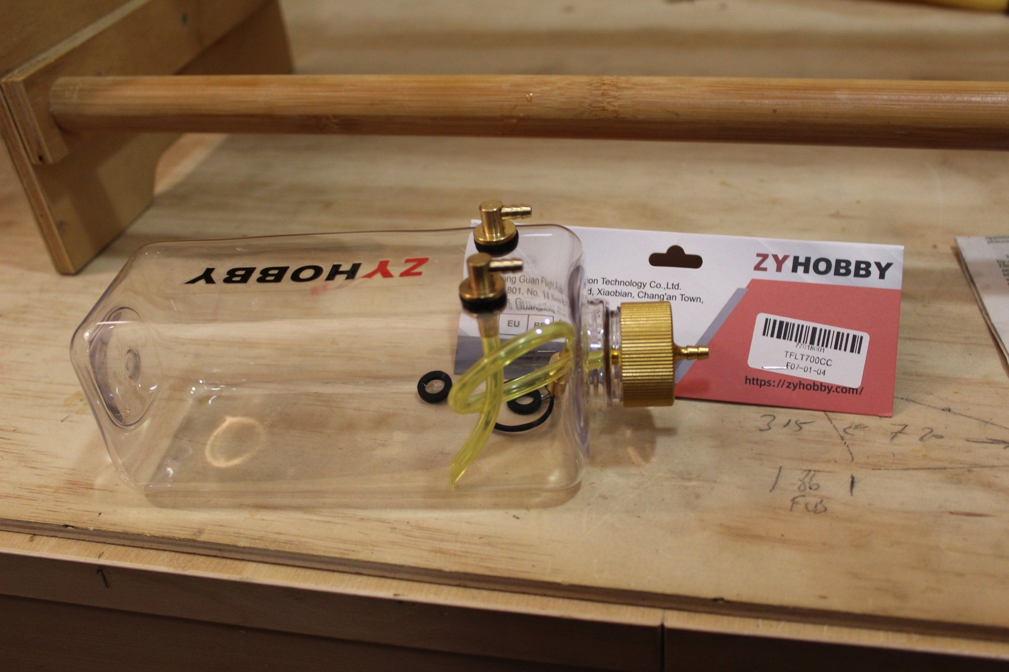
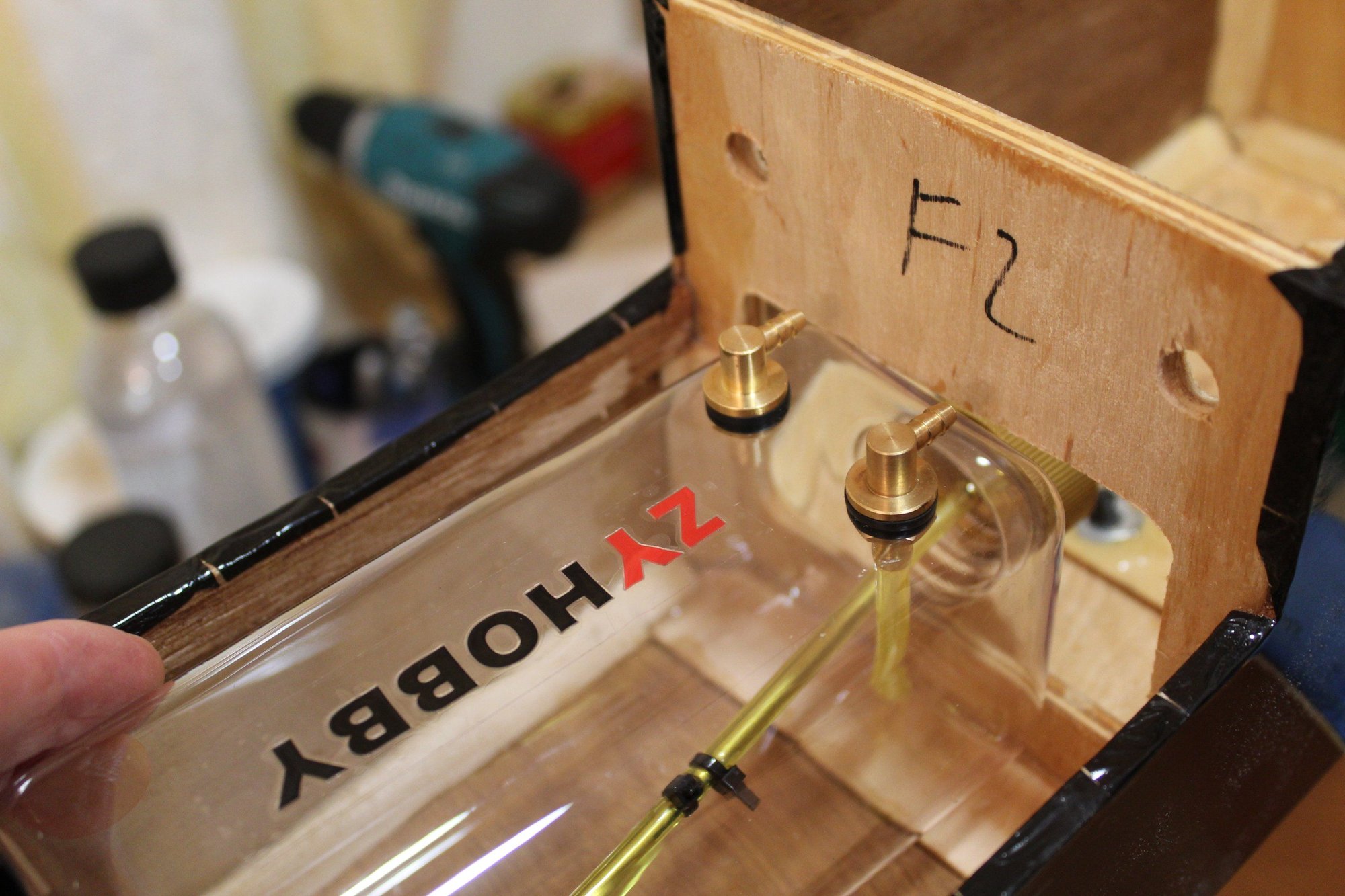
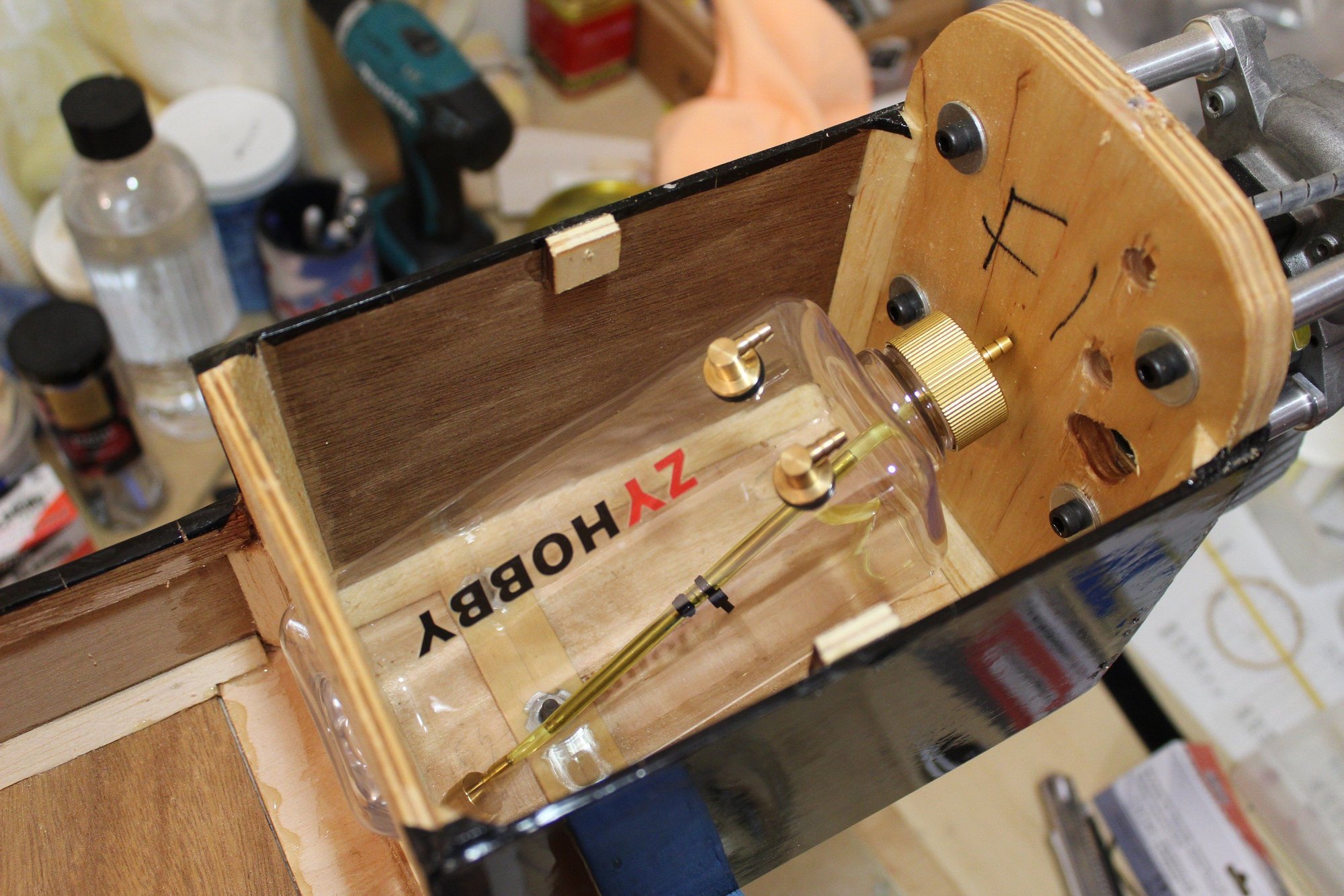
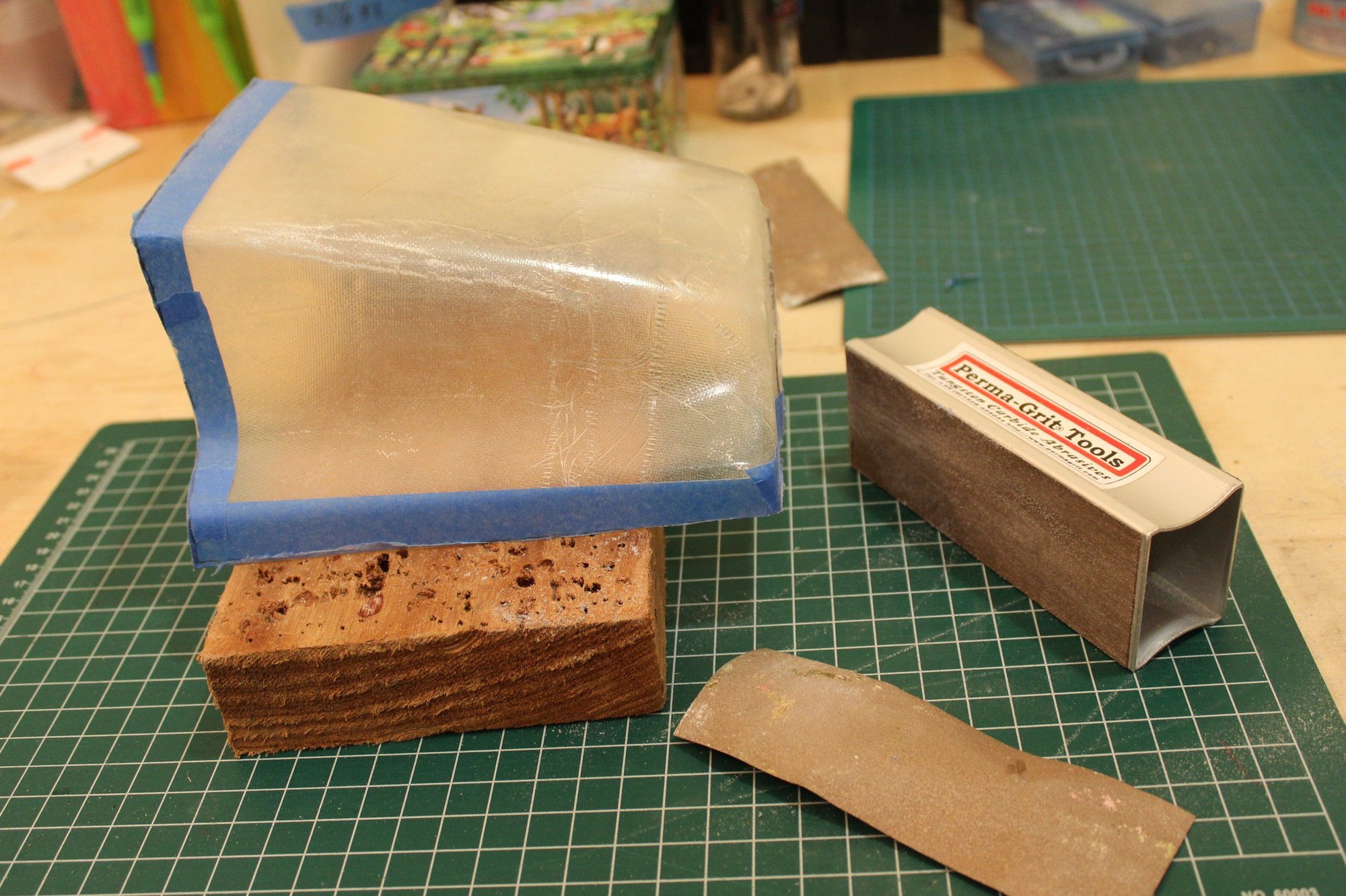
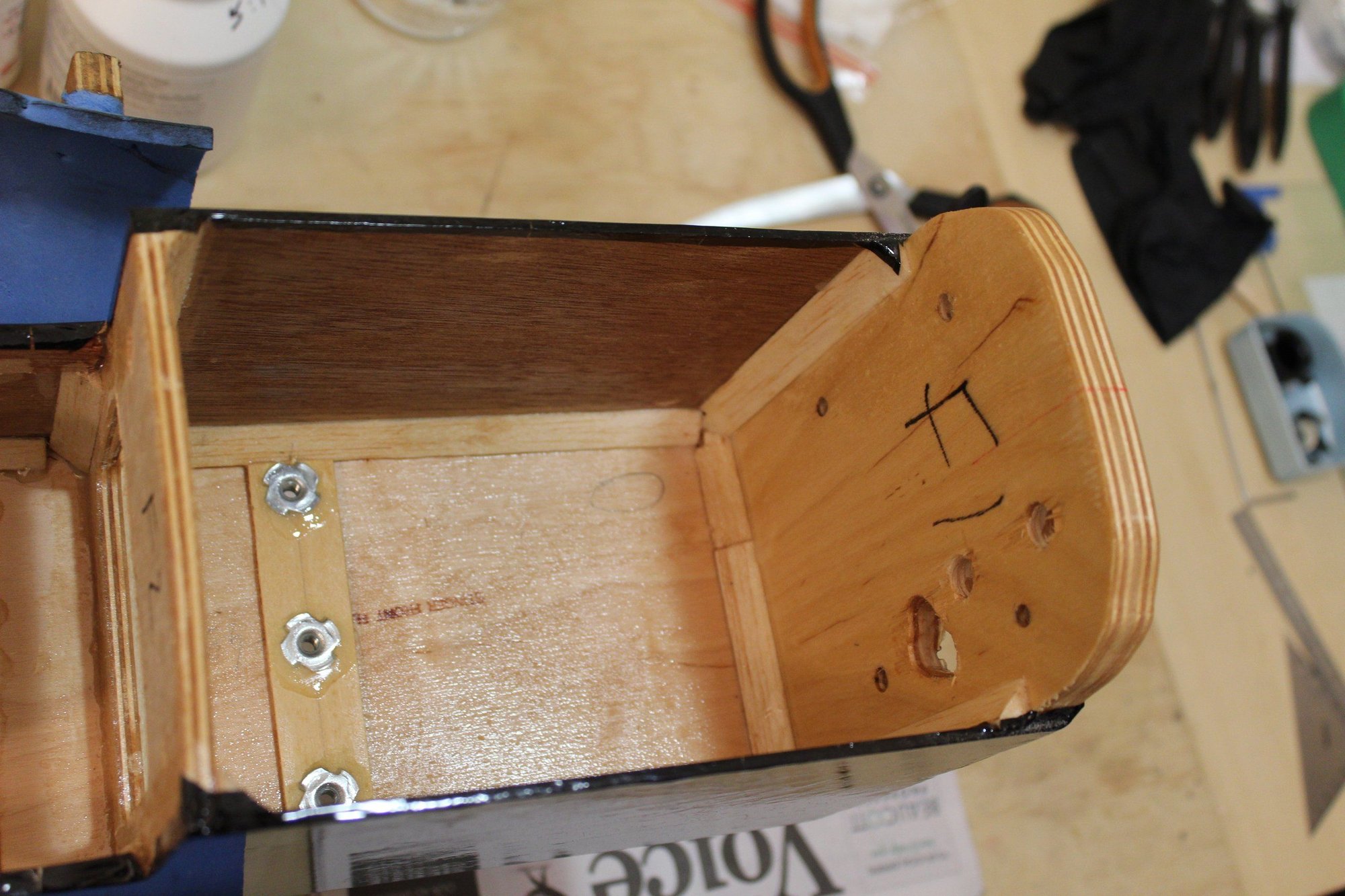
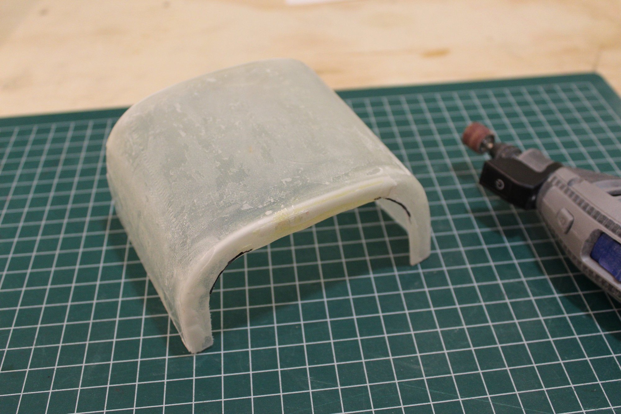
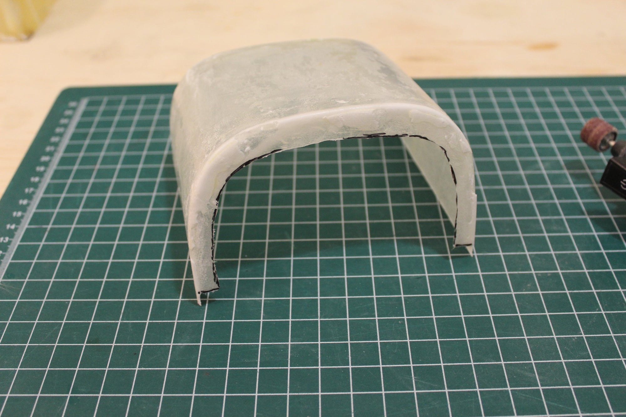
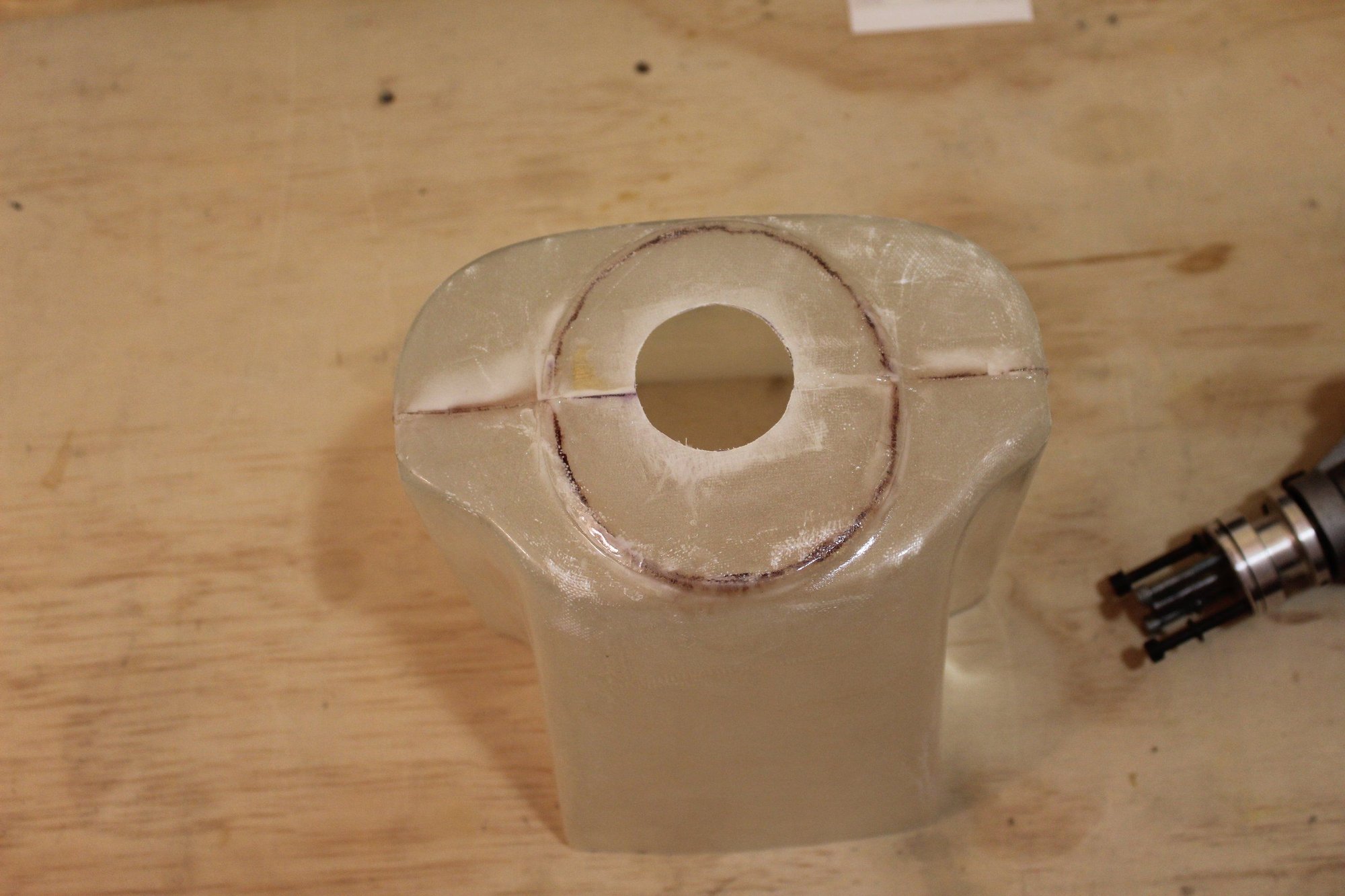
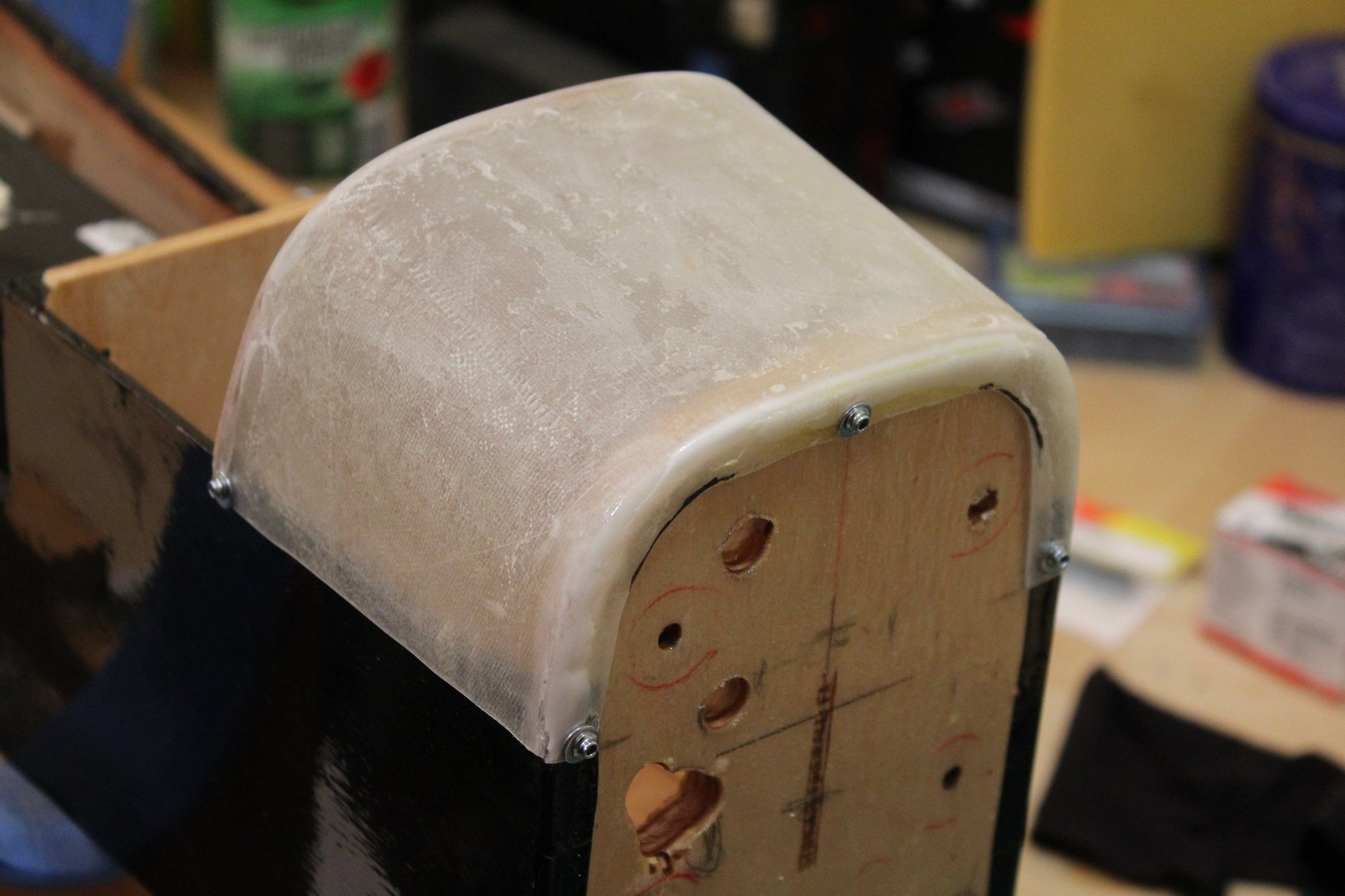
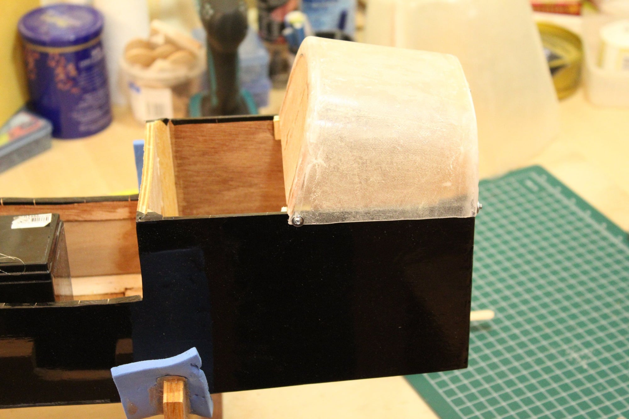
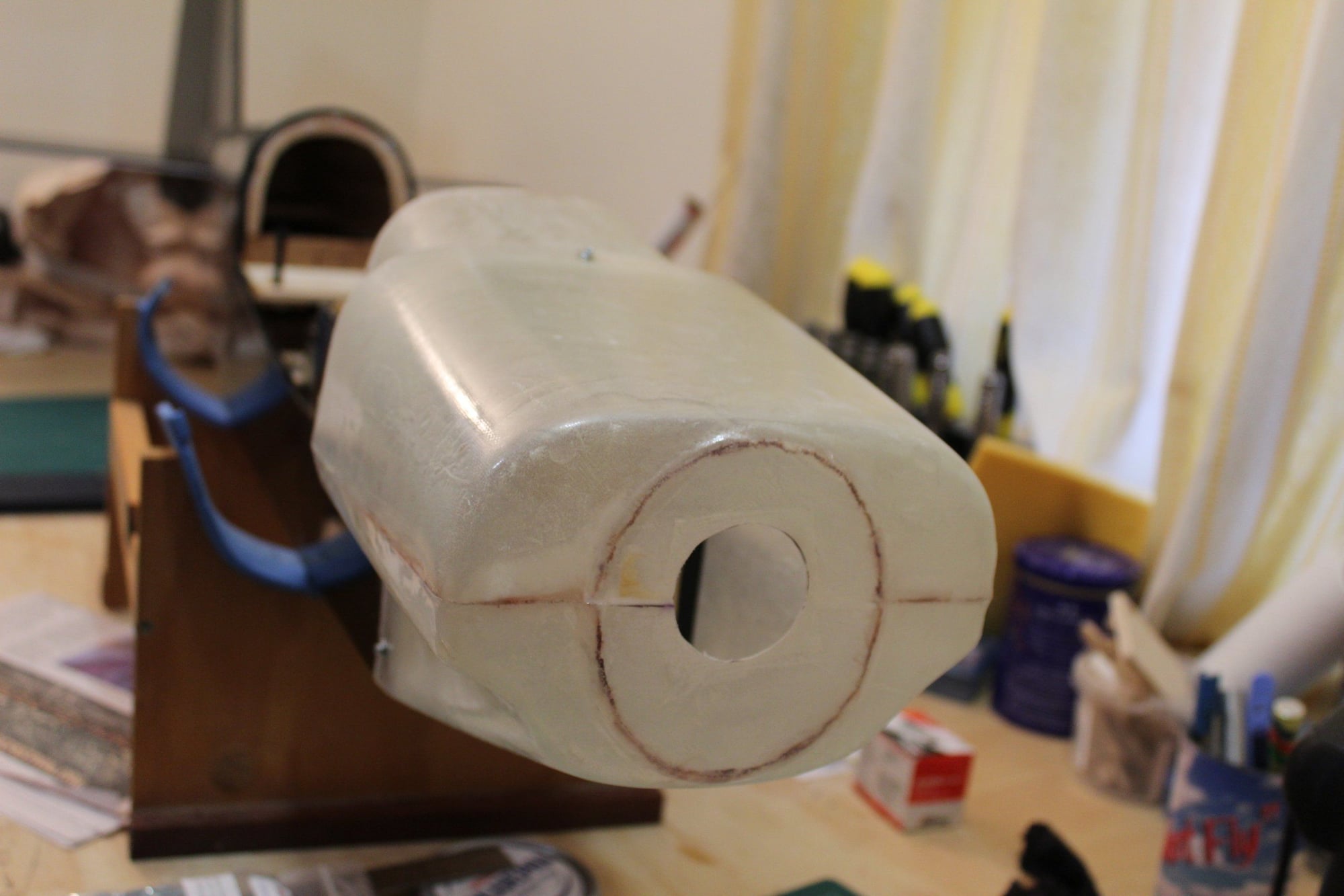
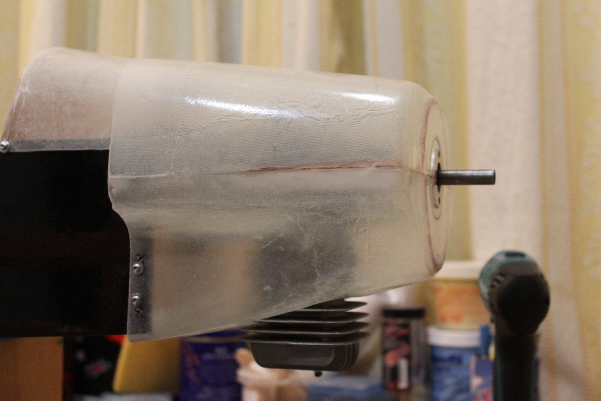
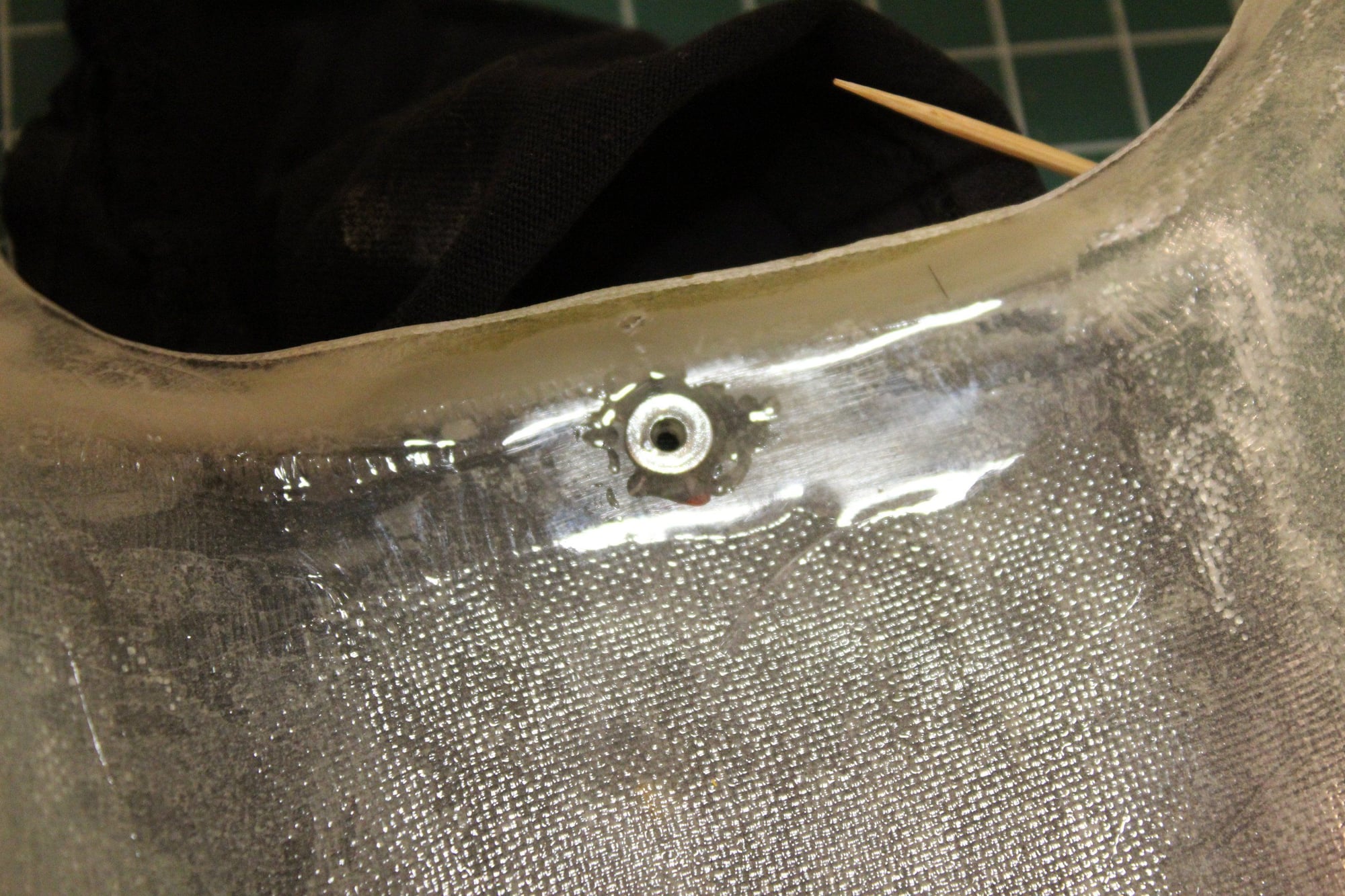
I marked the engine shaft exit location from the firewall and cut the required hole. I then cleaned the tank cover from the mould filler that stuck to it and fitted the tank filler into place. I made it removable (the kit calls for it to be glued) to allow for the fuel tank easy maintenance and the installation of the ignition battery and ignition module as close to the firewall as possible as I predict a tail heavy aeroplane with my lighter engine.


Cheers,
Eran
Cheers,
Eran
03-05-2024, 05:27 PM
#92
Thread Starter
Join Date: Jun 2008
Location: Perth WA, AUSTRALIA
Posts: 1,208
Likes: 0
Received 12 Likes
on
12 Posts
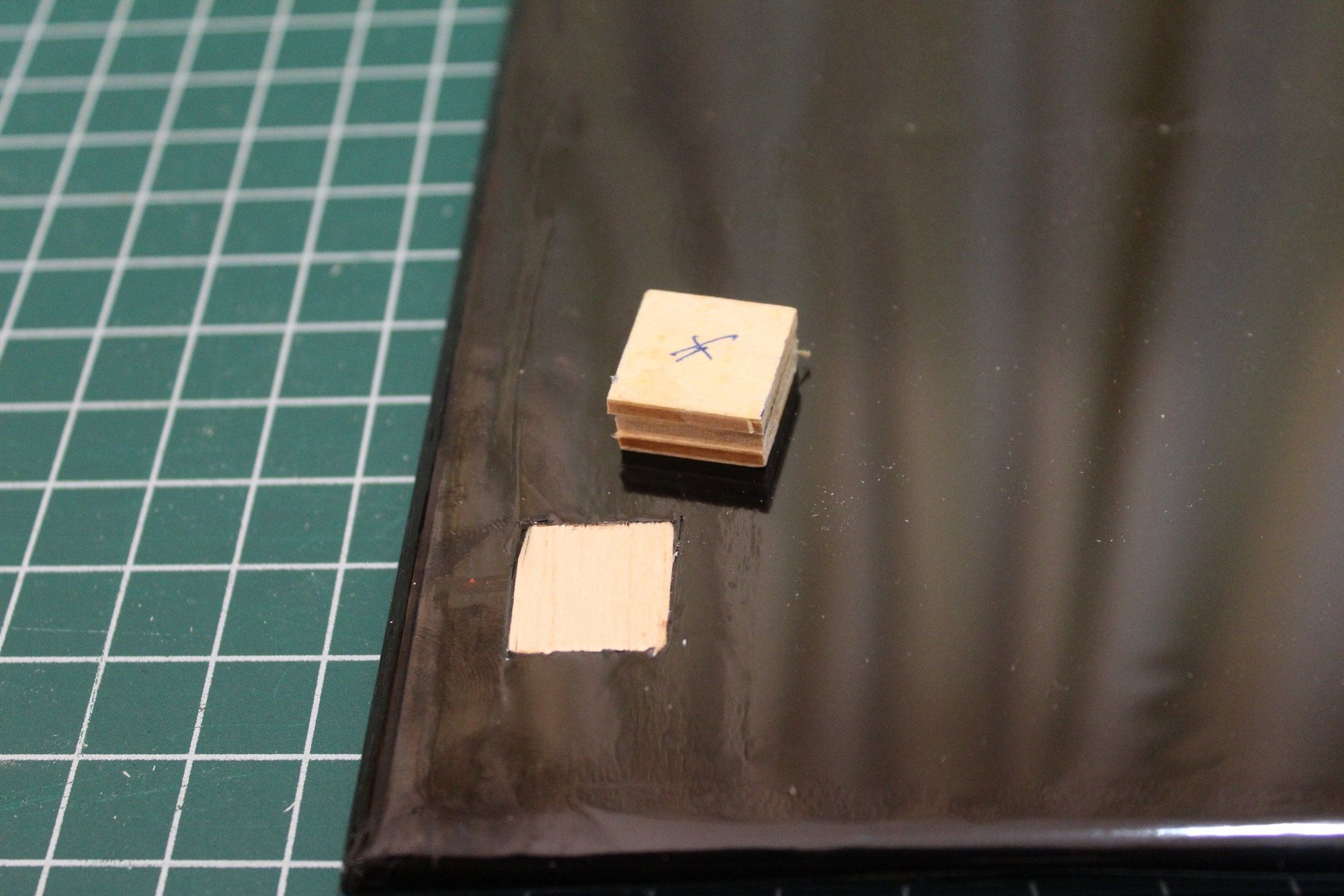
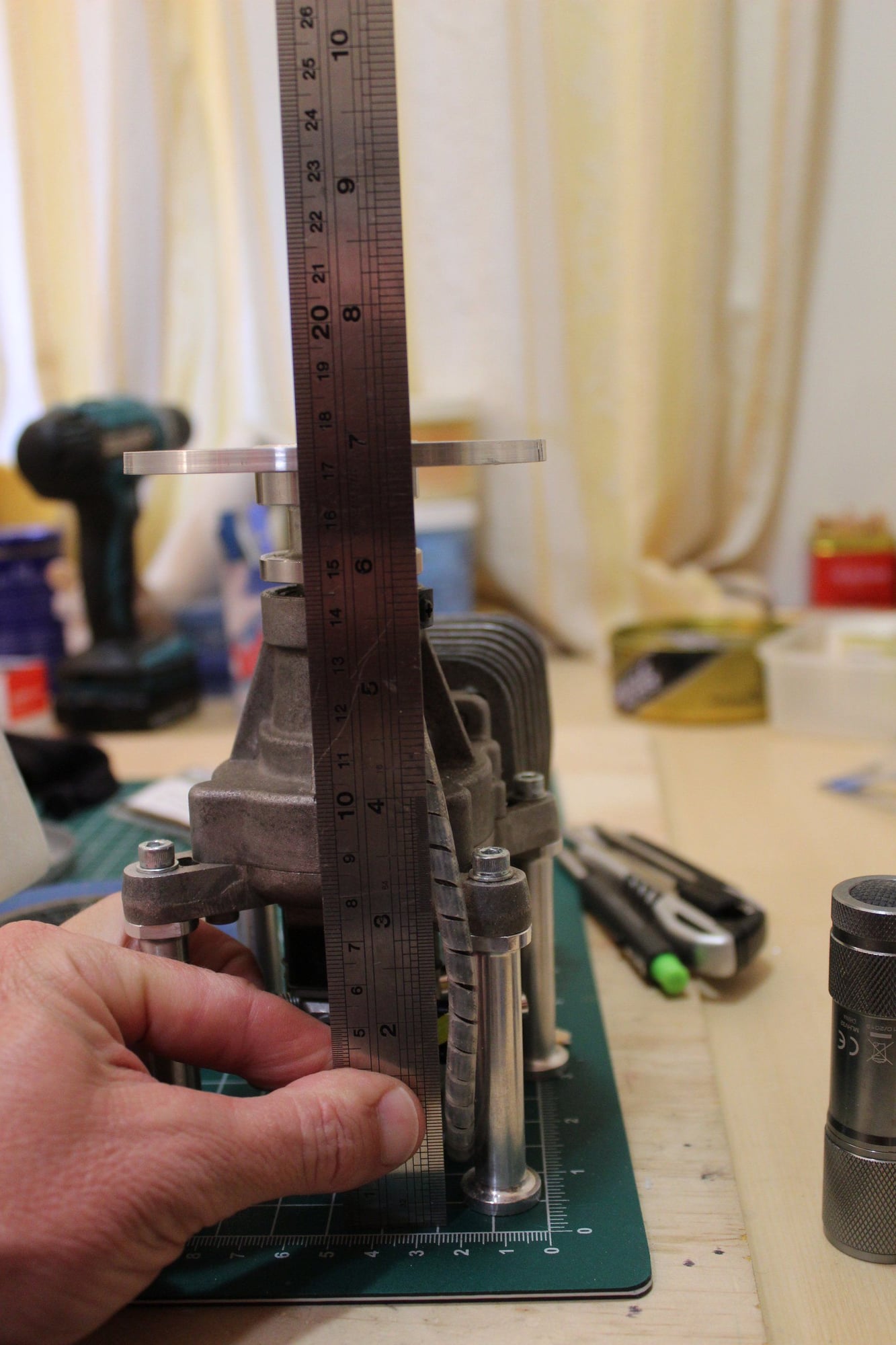
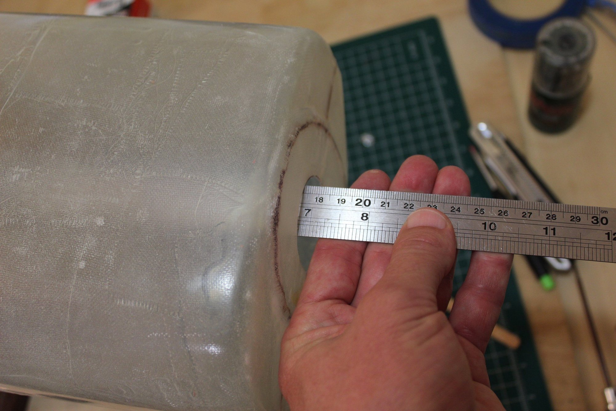
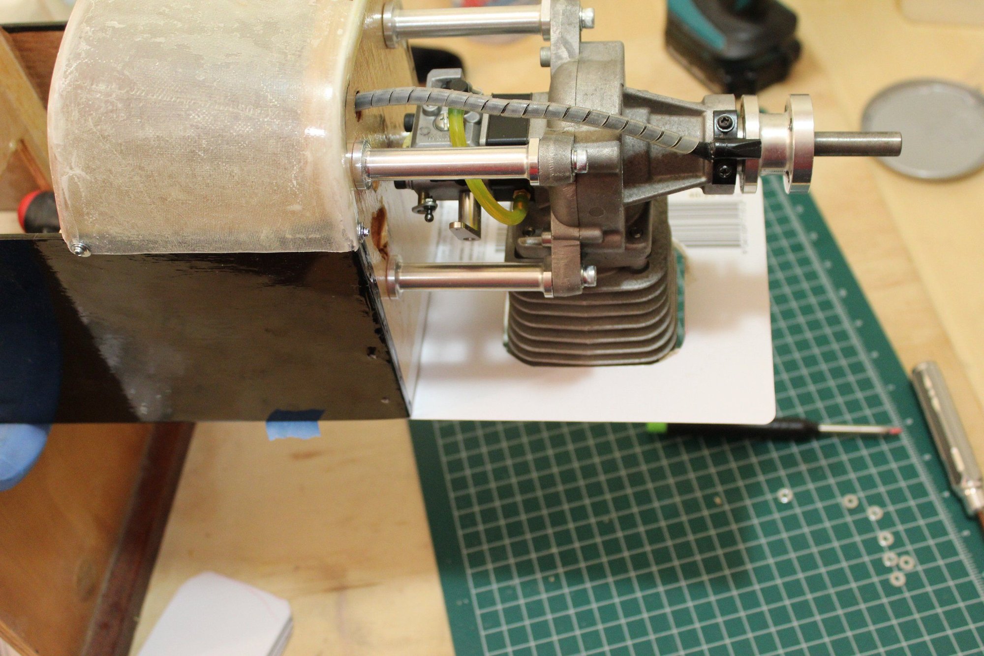
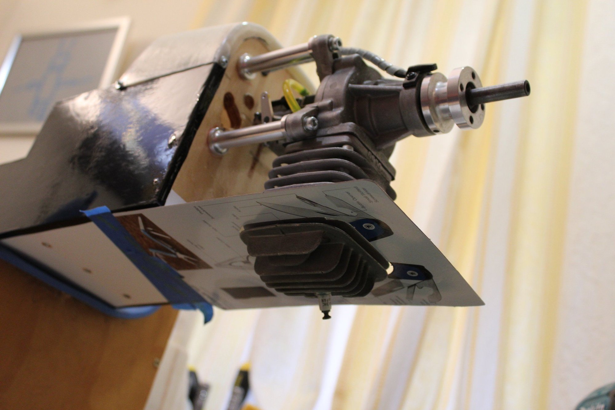
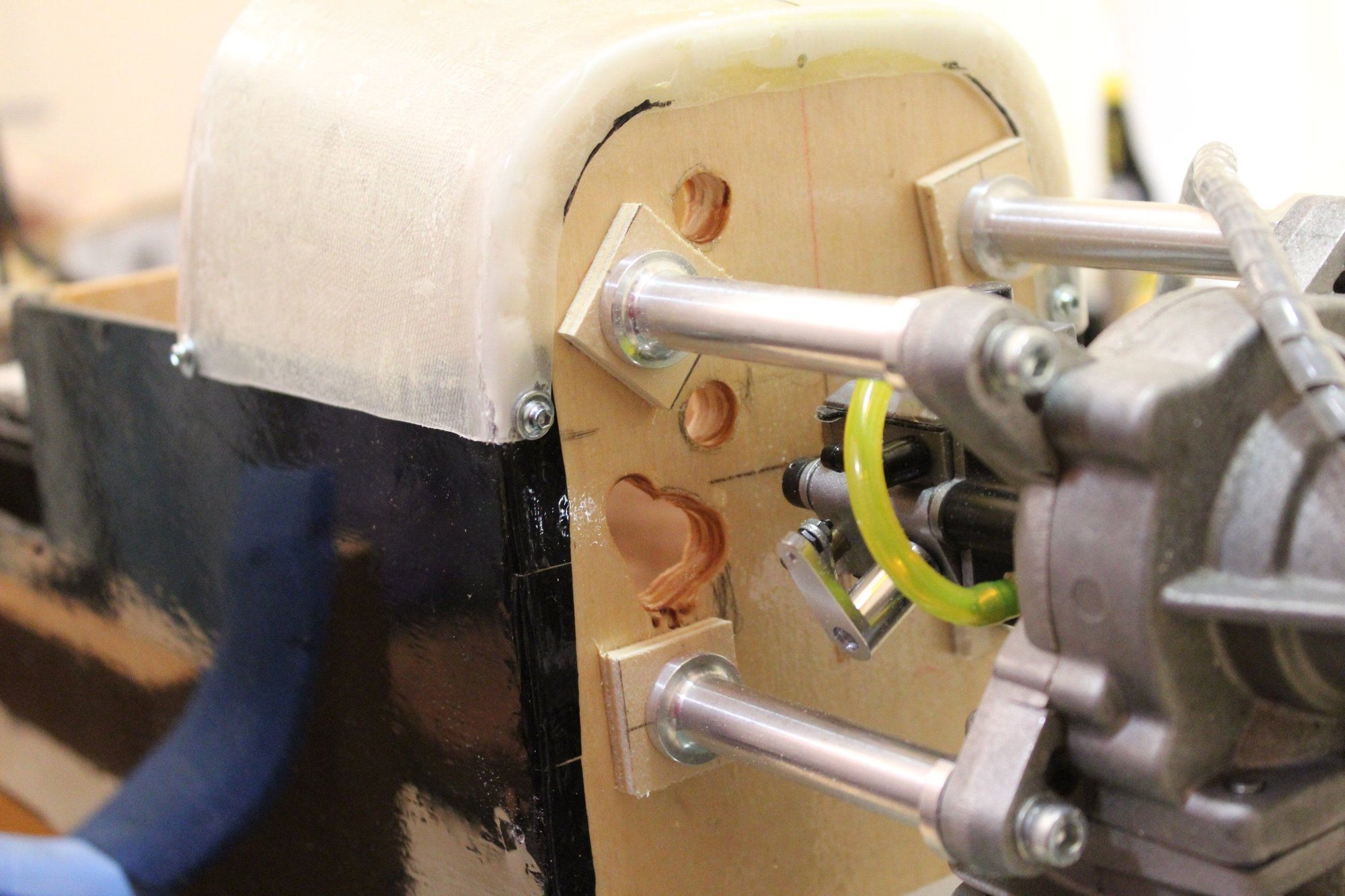
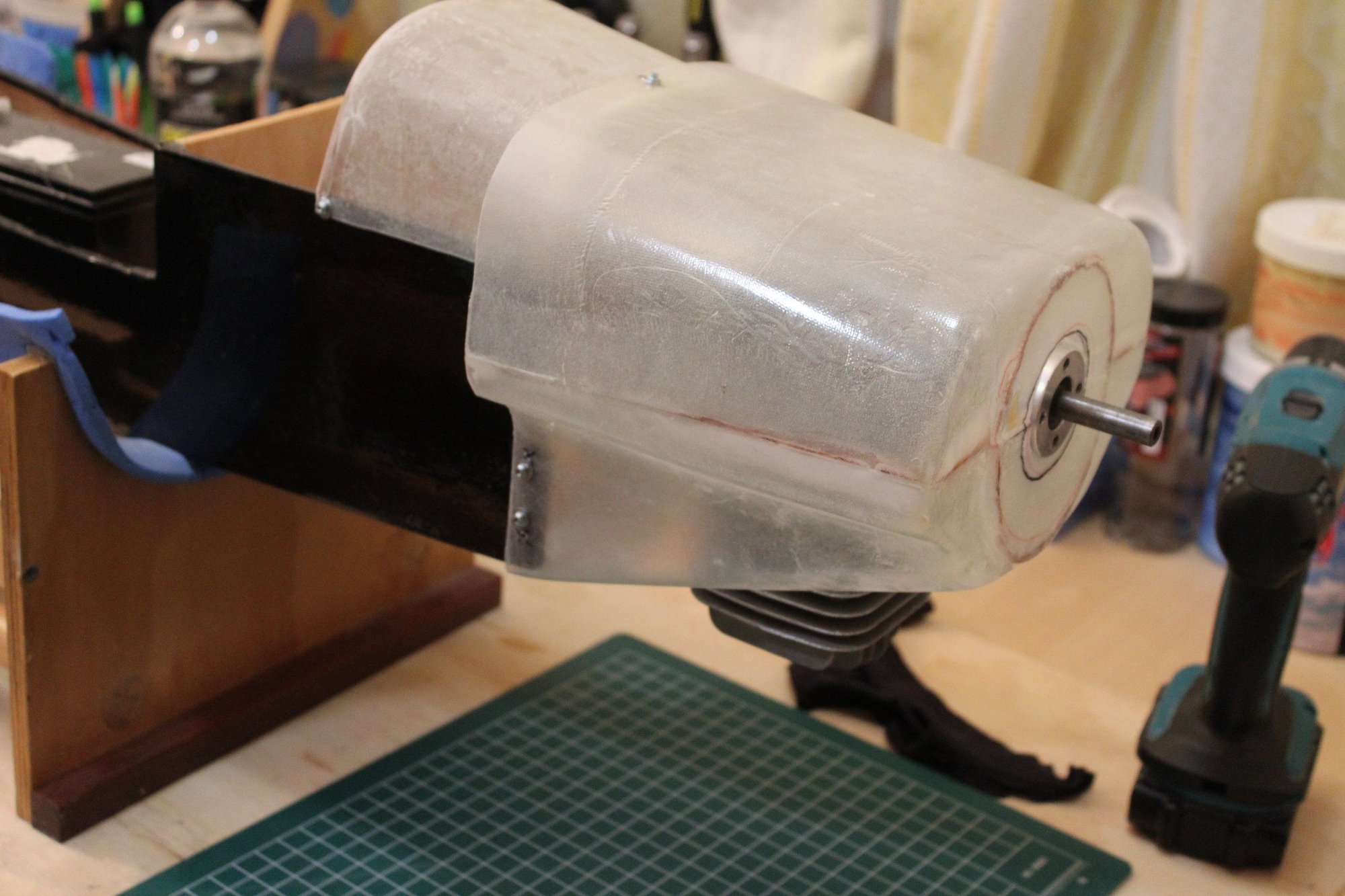
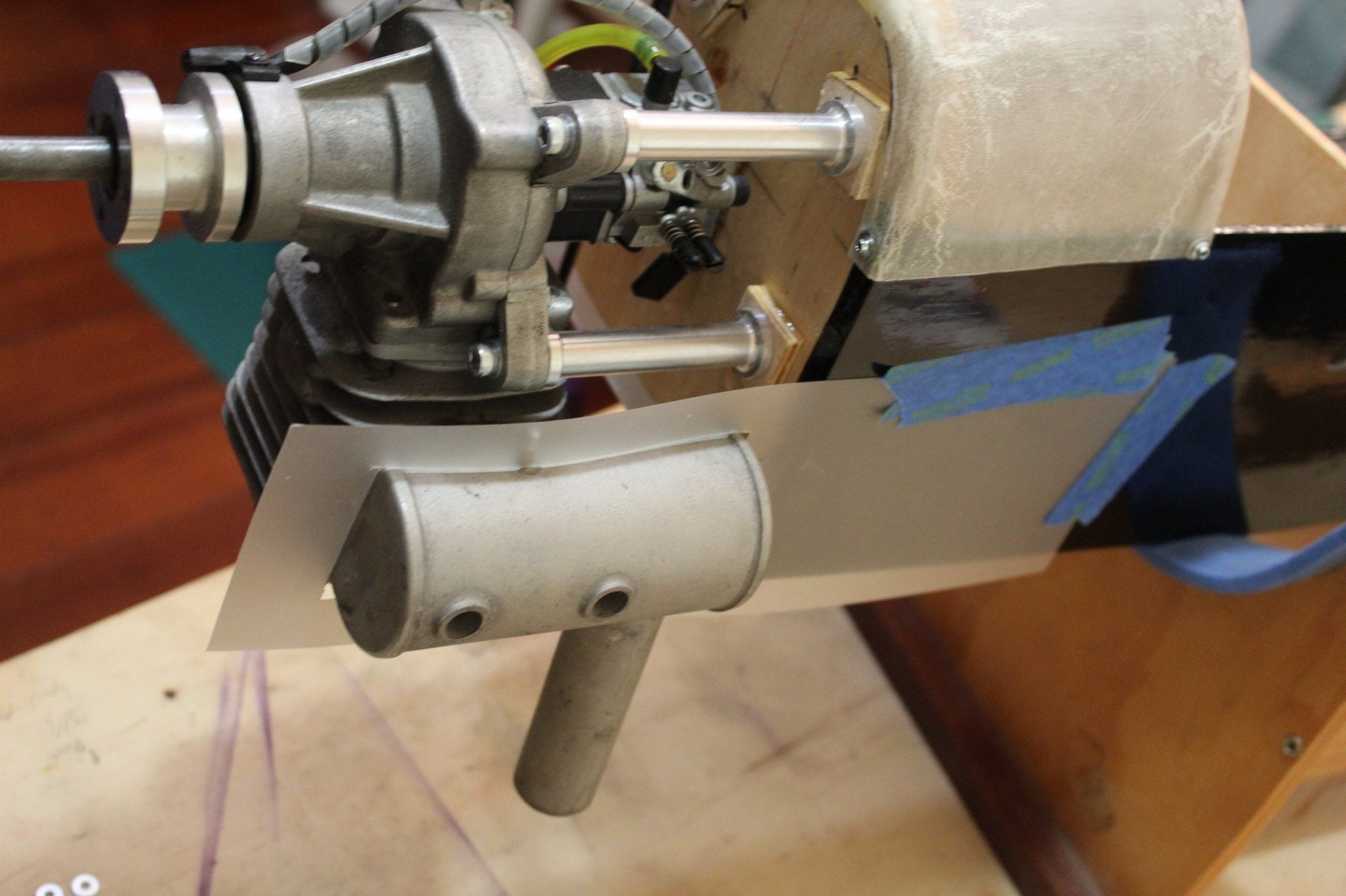
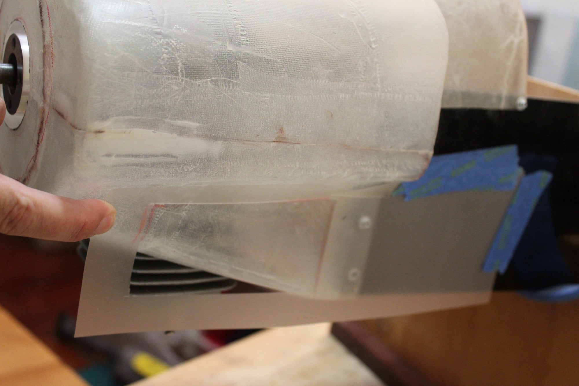
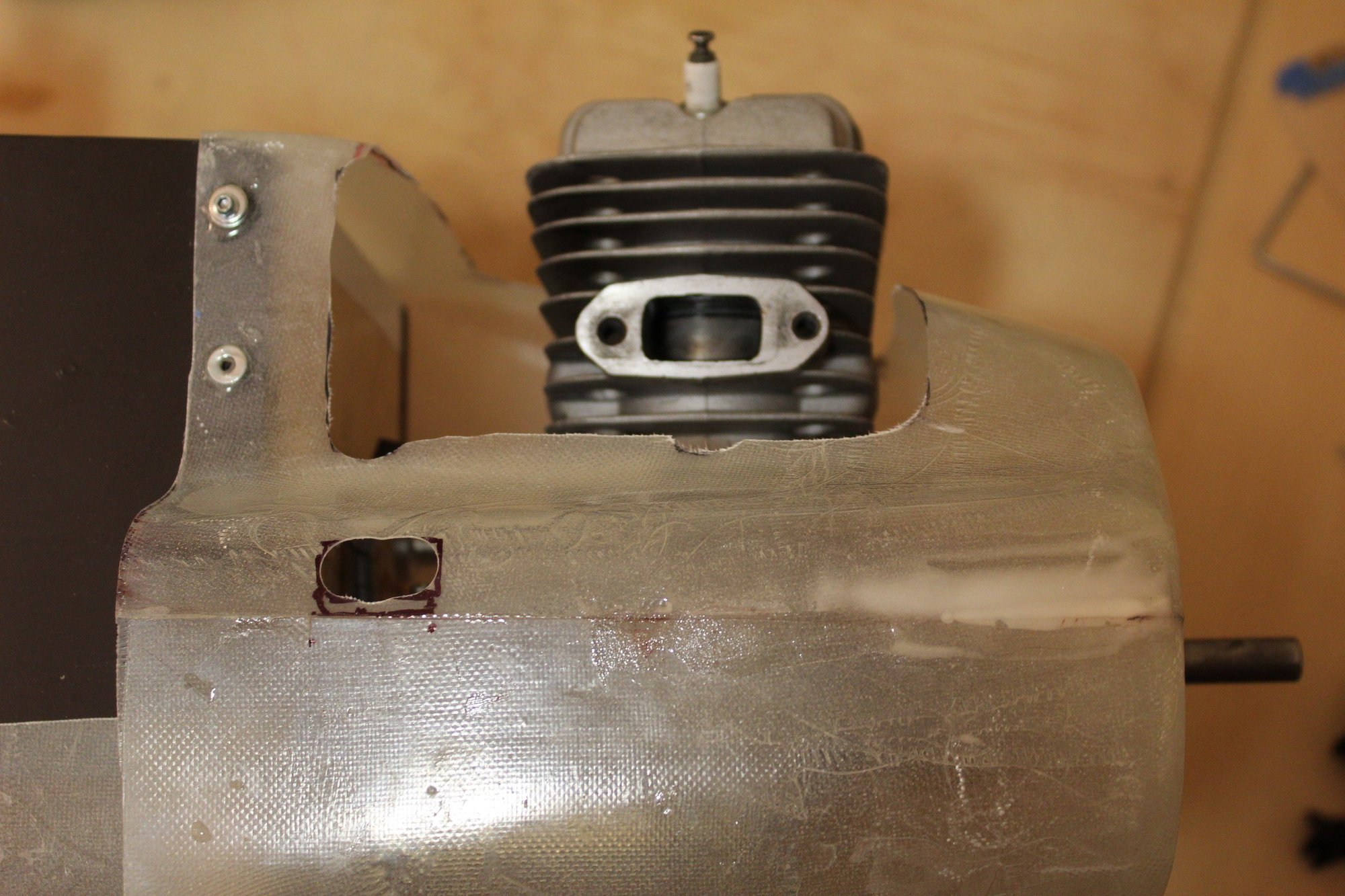
Fitting the cowl, a quick measure of the distance from the end of the stand-offs to have correct prop clearance and then mounting the engine and making a cardboard template transfer for the cylinder head cut out.
After trail fitting, I needed some spacers for the stand-offs for the prop to clear the cowl, which I cut out of Plywood.
Cheers,
Eran
After trail fitting, I needed some spacers for the stand-offs for the prop to clear the cowl, which I cut out of Plywood.
Cheers,
Eran
03-06-2024, 07:50 PM
#93
Thread Starter
Join Date: Jun 2008
Location: Perth WA, AUSTRALIA
Posts: 1,208
Likes: 0
Received 12 Likes
on
12 Posts
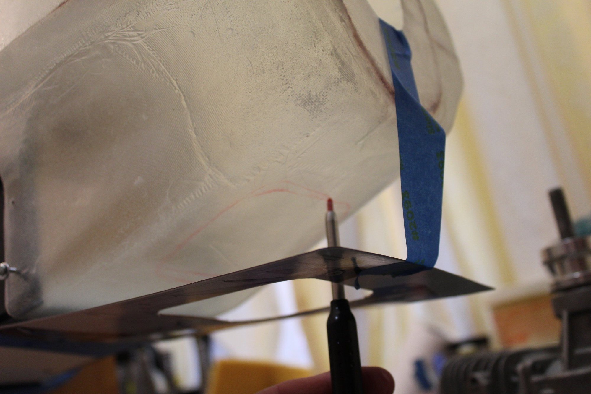
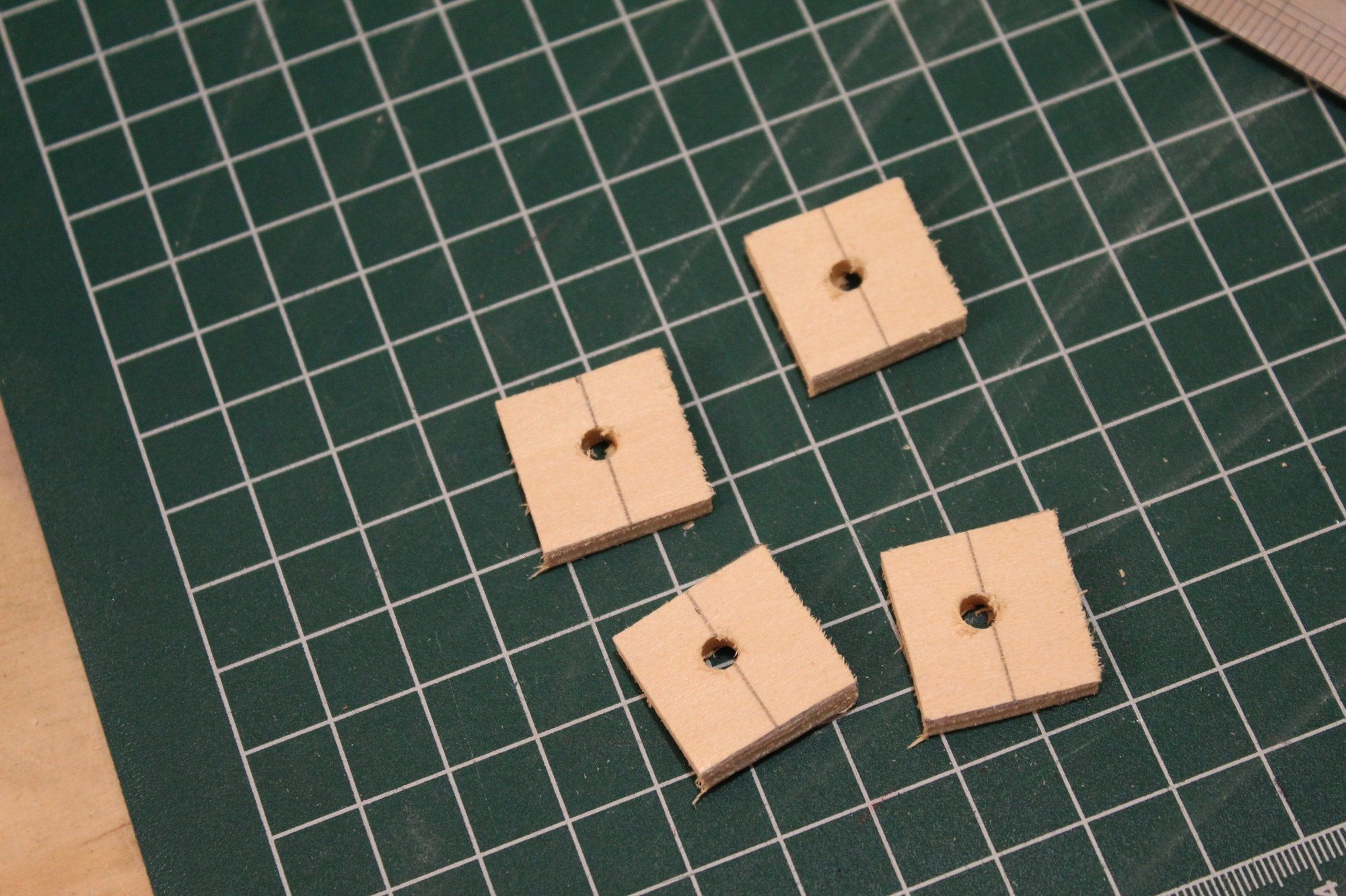
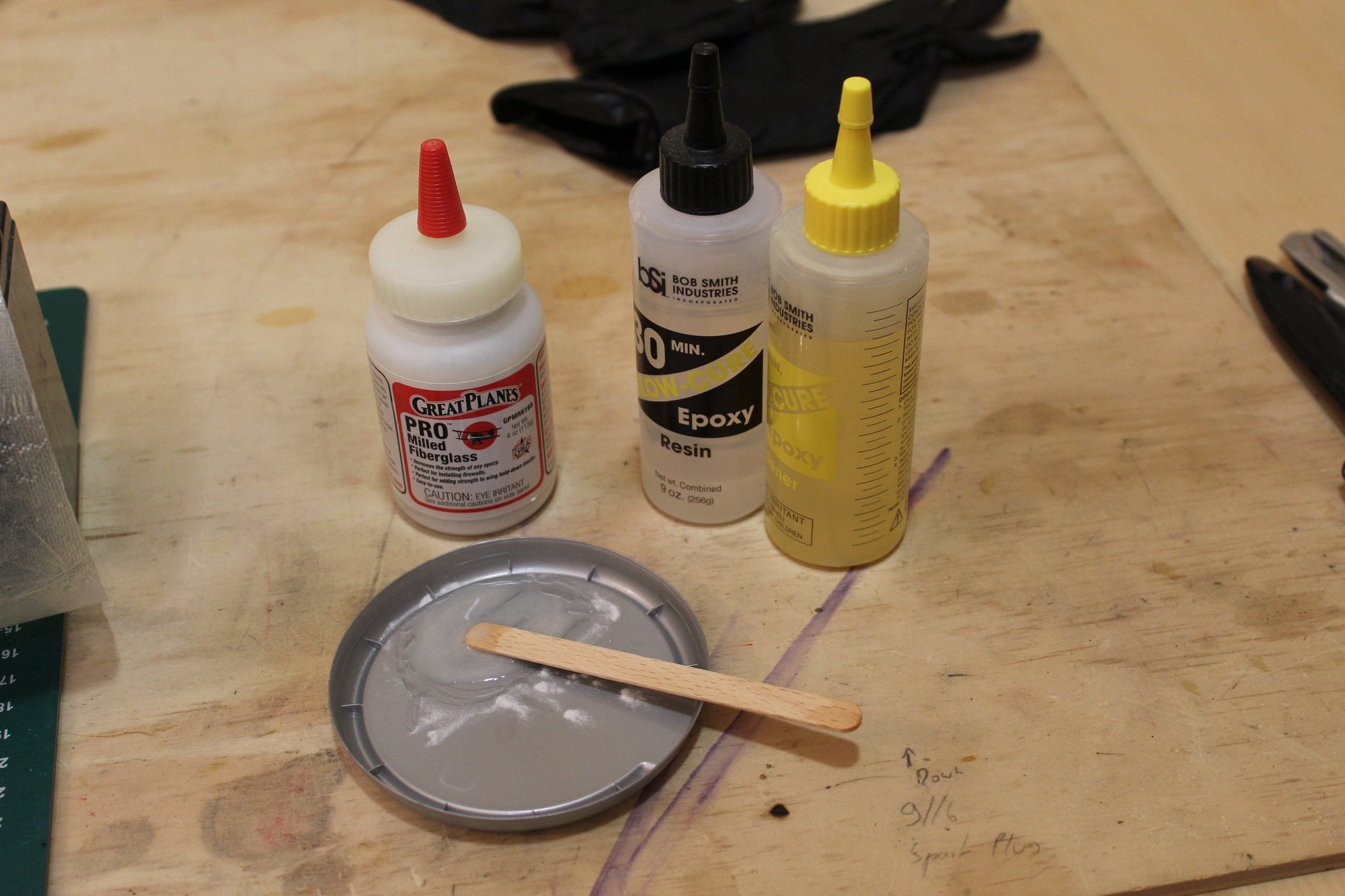
To protect the fibreglass from expanding due to vibrations at the screw holes I glued washers around the holes.
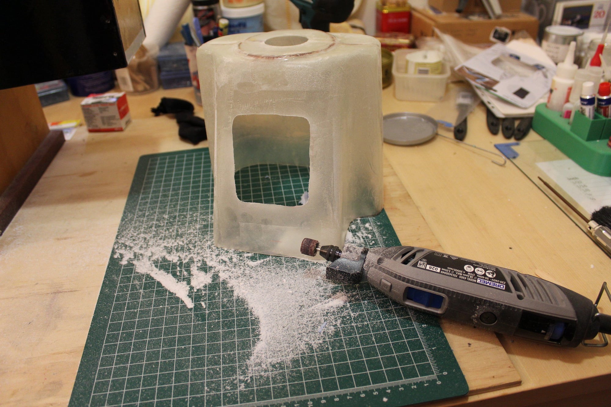
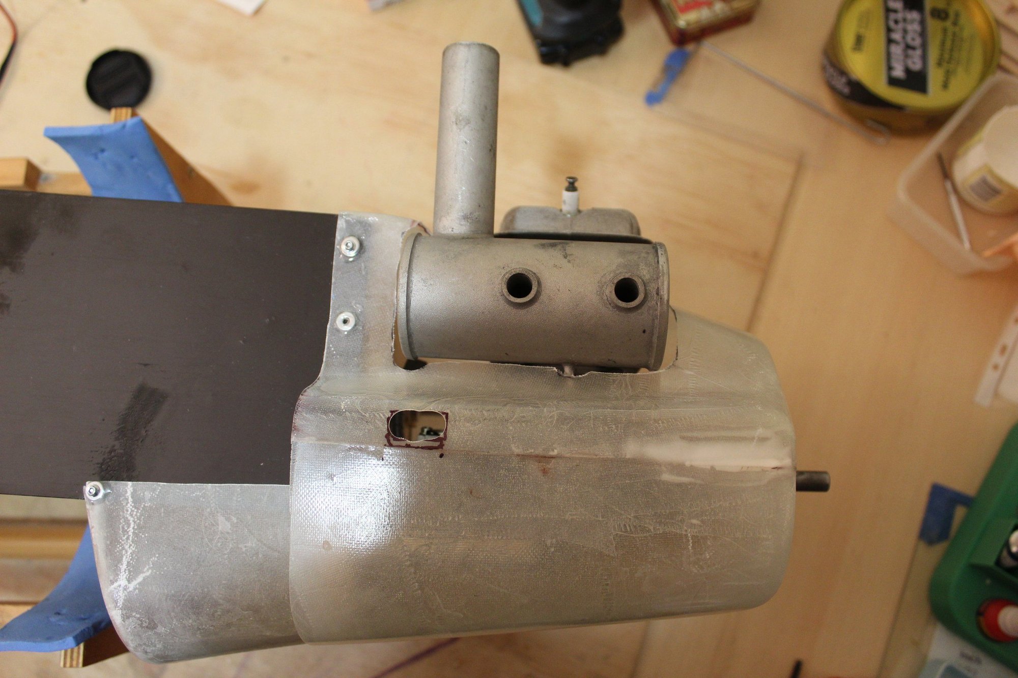
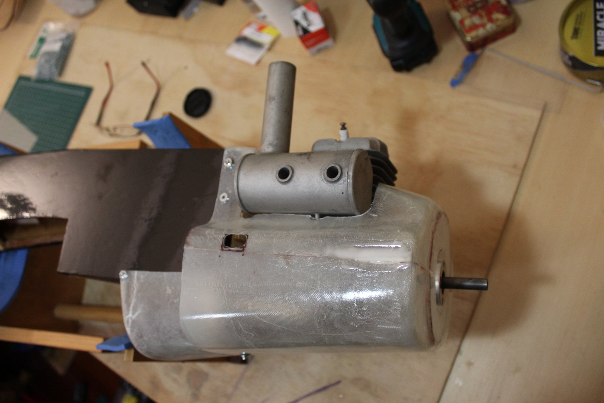
Once dry, I marked the muffler exit hole on the cowl and cut it, as well as a hole to access to the engine tuning screws.
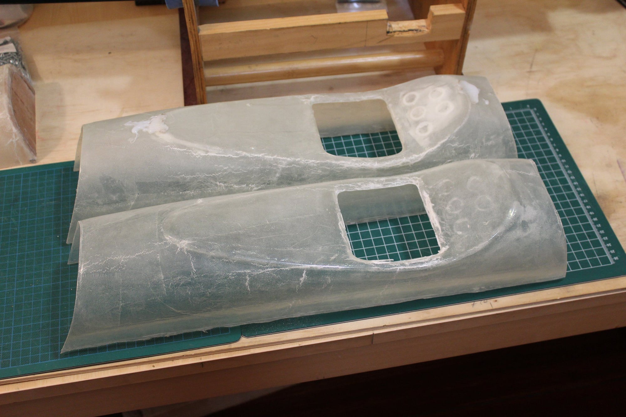
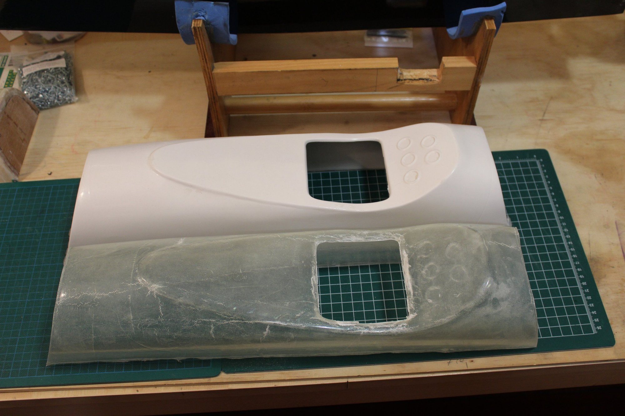
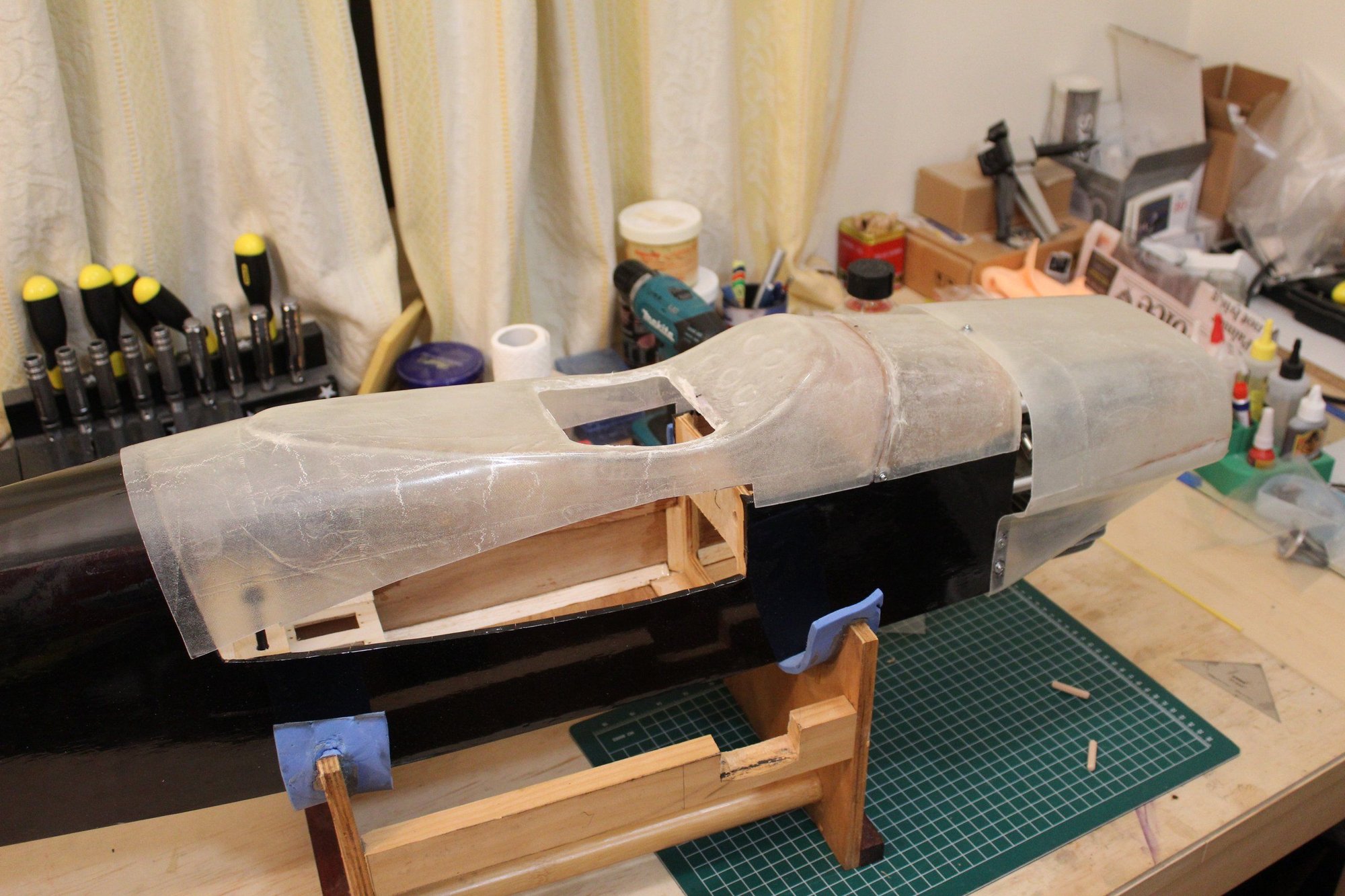
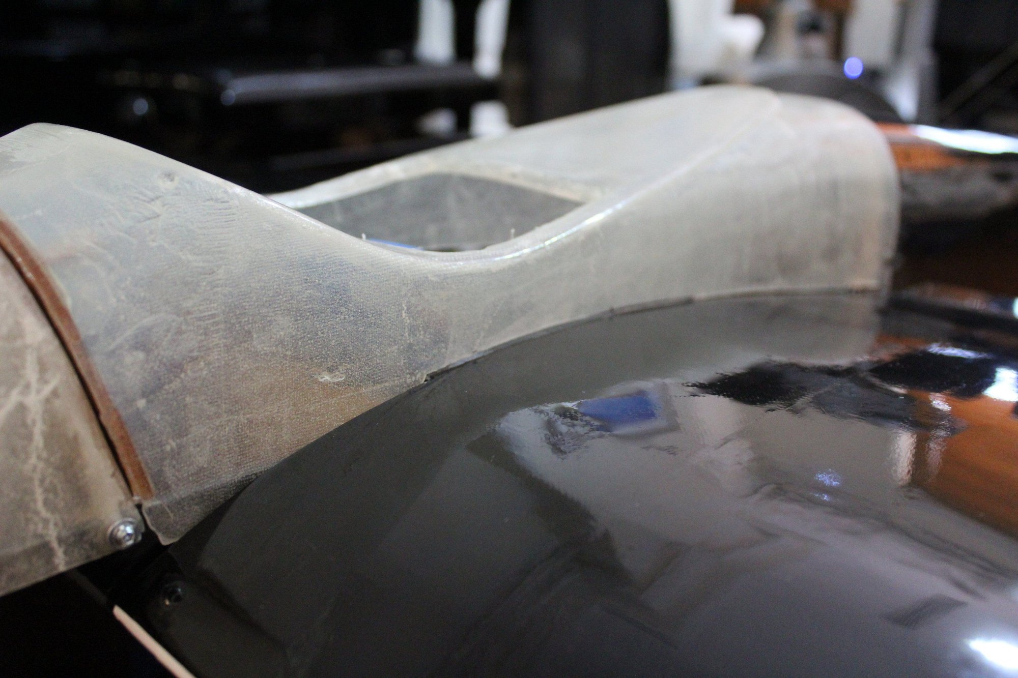
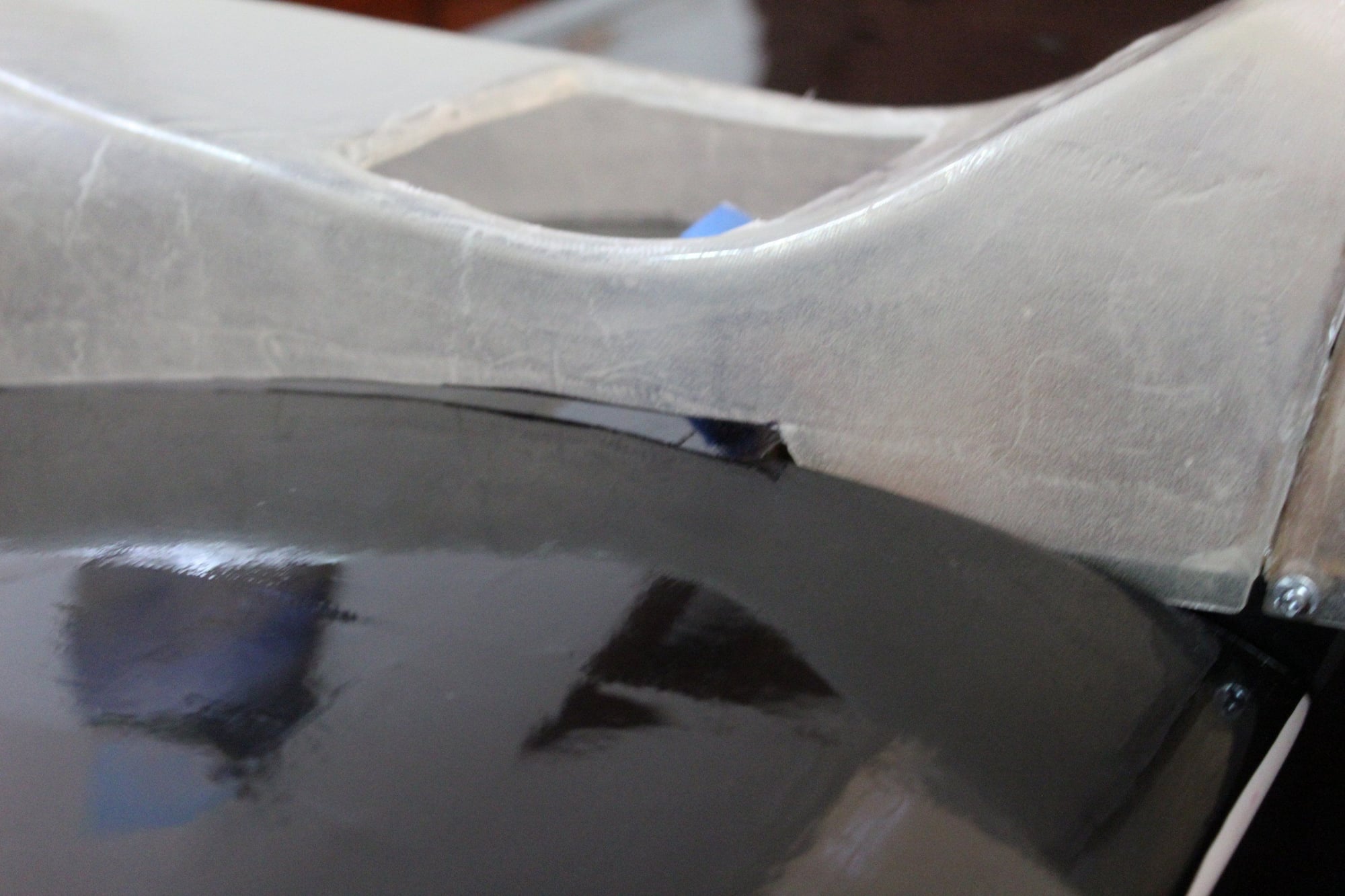
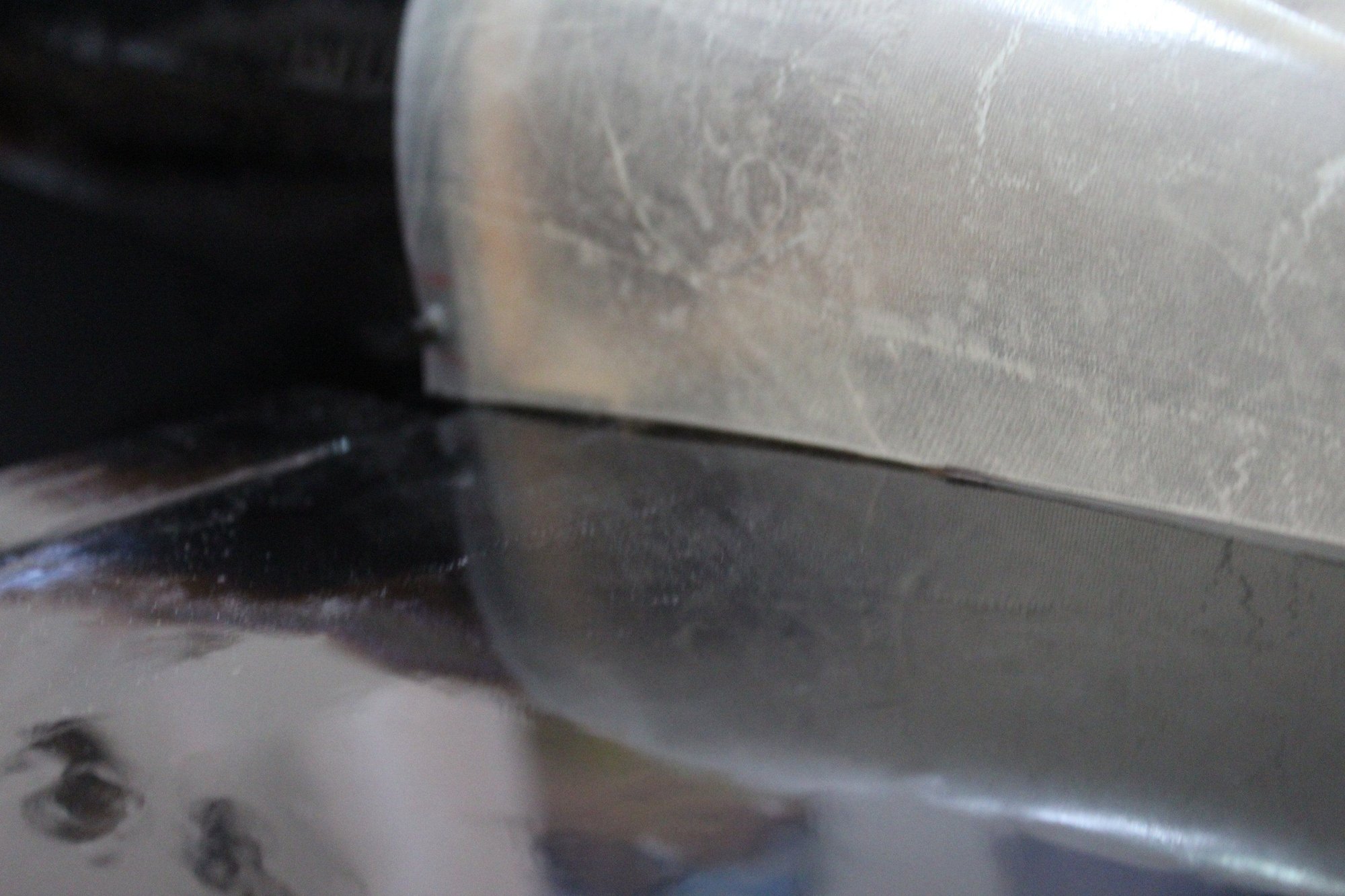
Next, I inspected the wing cover / cockpit section part and mould which were collected after drying at my friends shed comparing the fibreglass part to the original ABS plastic cockpit section. It came out quite good.

Cheers,
Eran
Once dry, I marked the muffler exit hole on the cowl and cut it, as well as a hole to access to the engine tuning screws.
Next, I inspected the wing cover / cockpit section part and mould which were collected after drying at my friends shed comparing the fibreglass part to the original ABS plastic cockpit section. It came out quite good.
Cheers,
Eran

 03-10-2024, 04:29 AM
#95
Thread Starter
Join Date: Jun 2008
Location: Perth WA, AUSTRALIA
Posts: 1,208
Likes: 0
Received 12 Likes
on
12 Posts
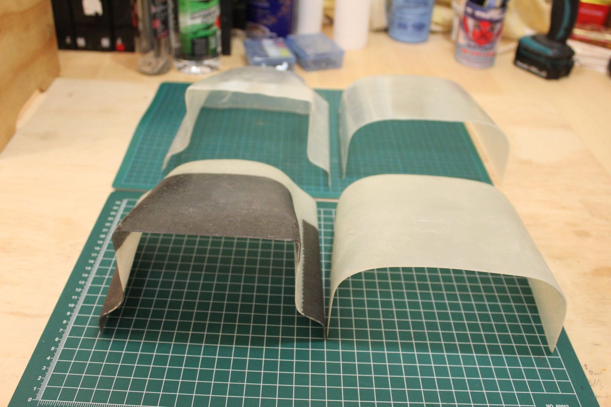
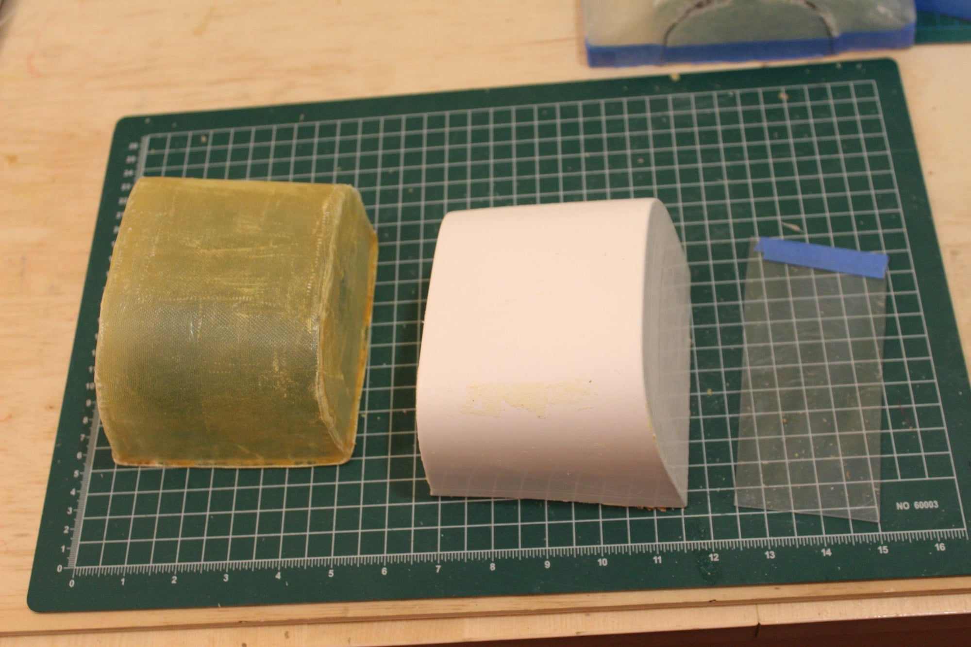
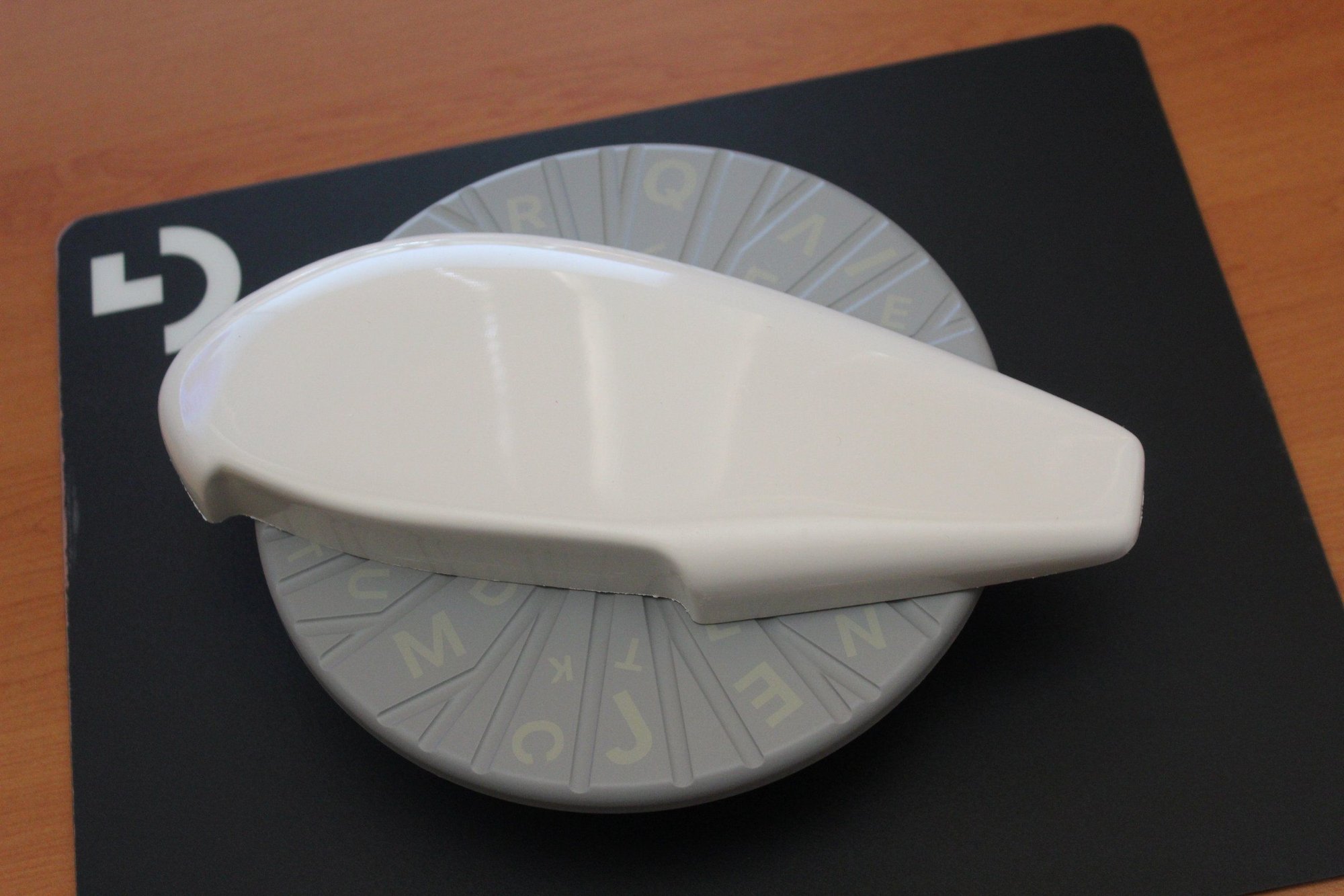
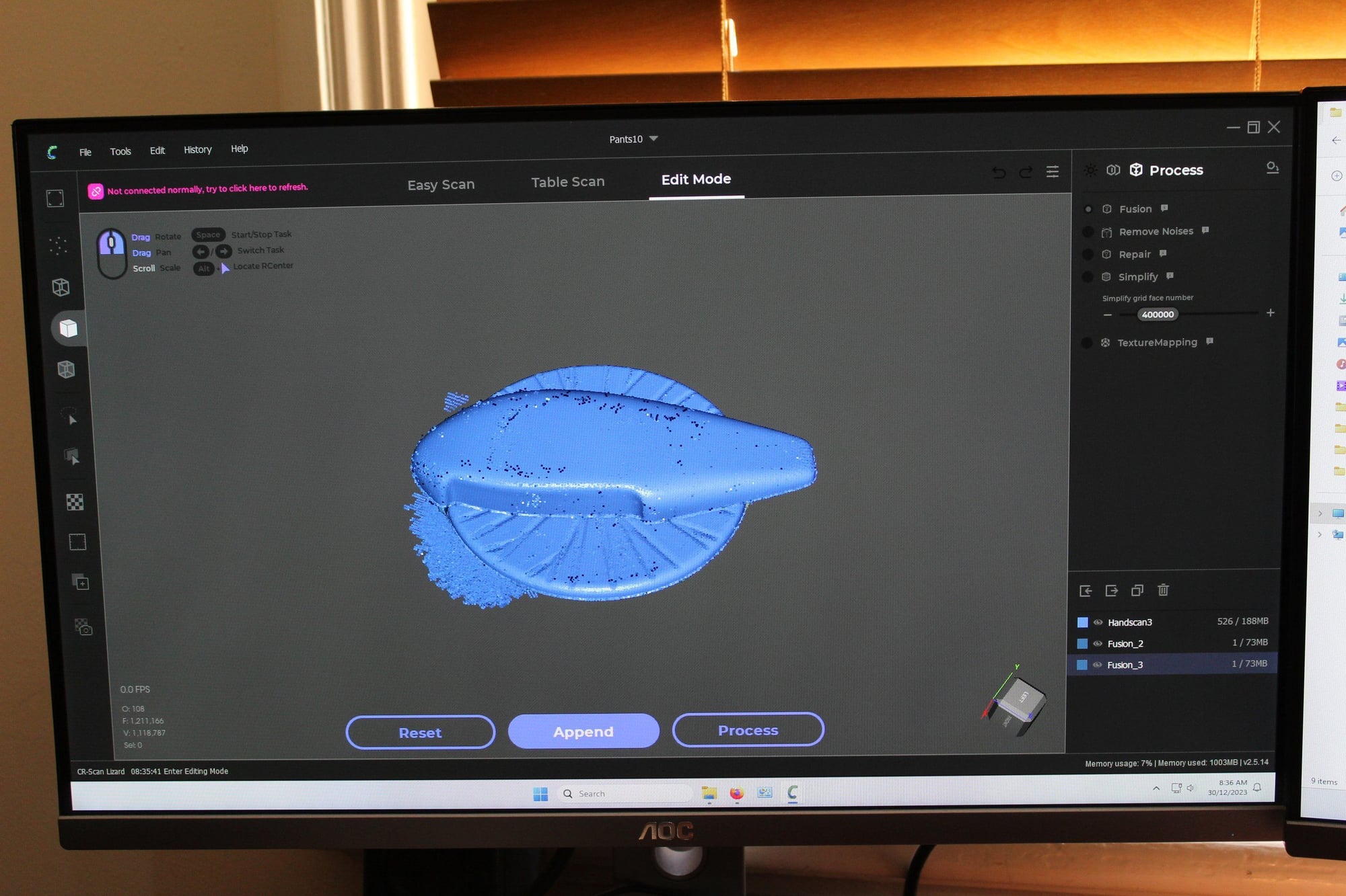
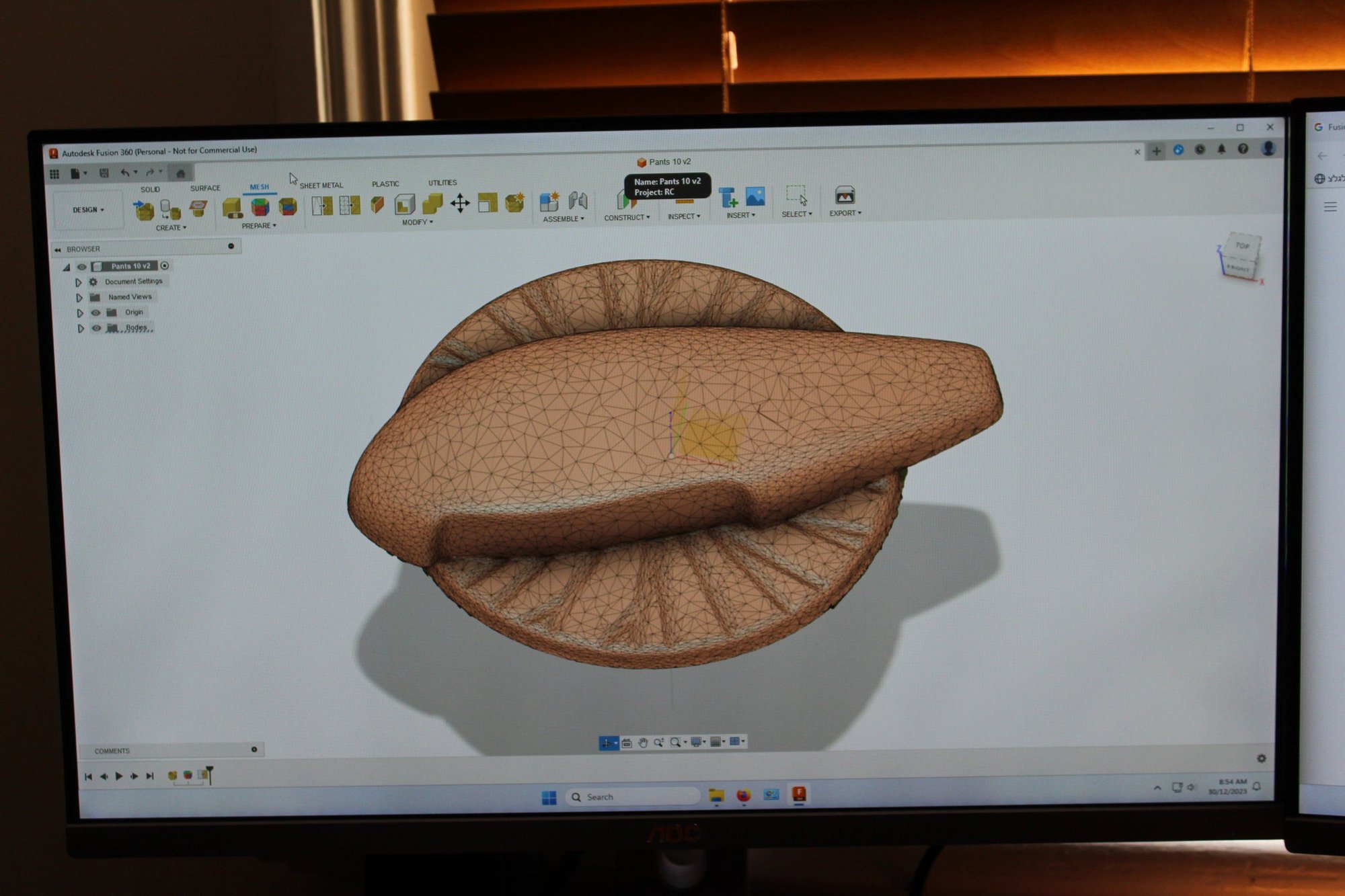
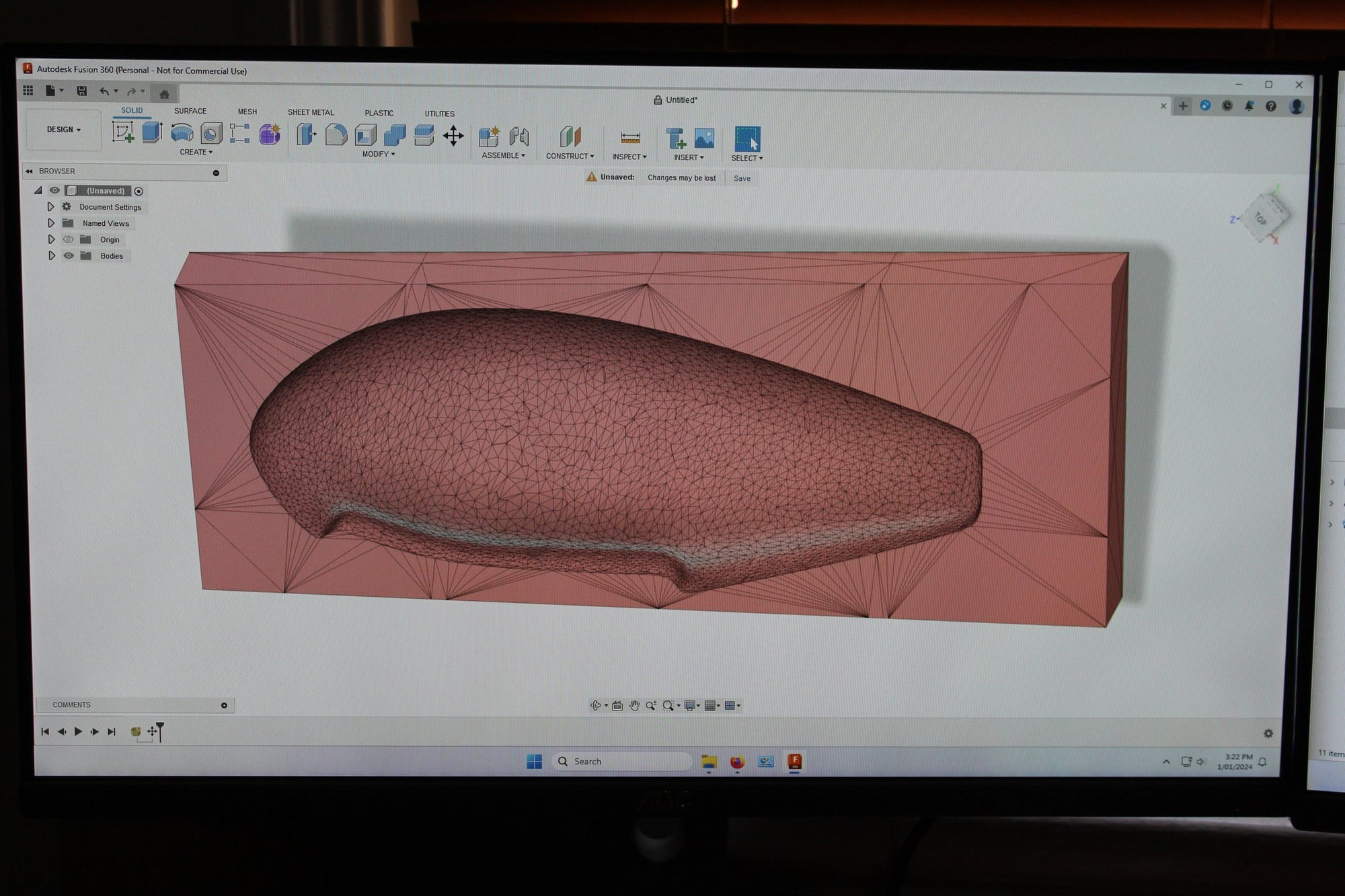
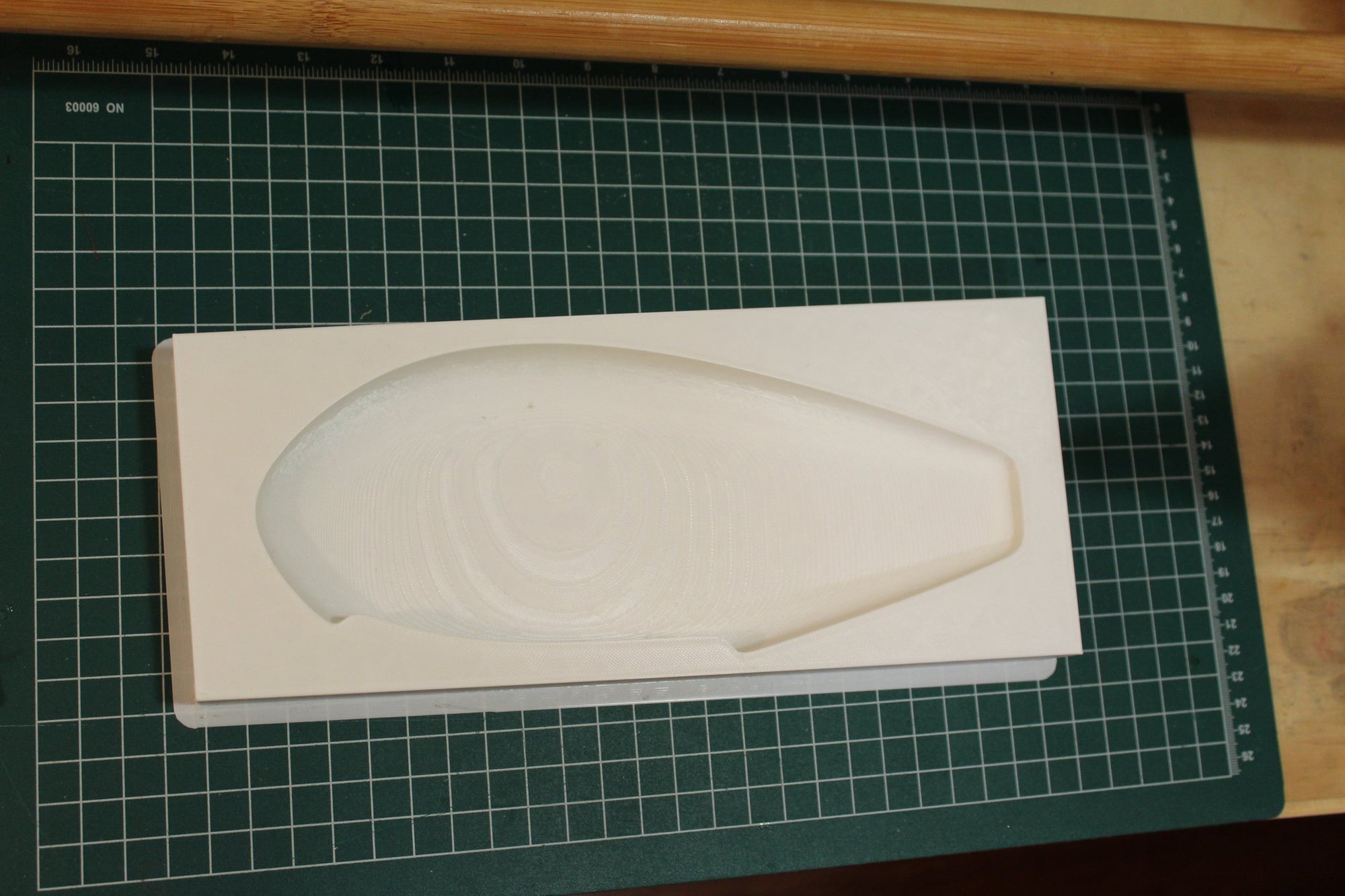
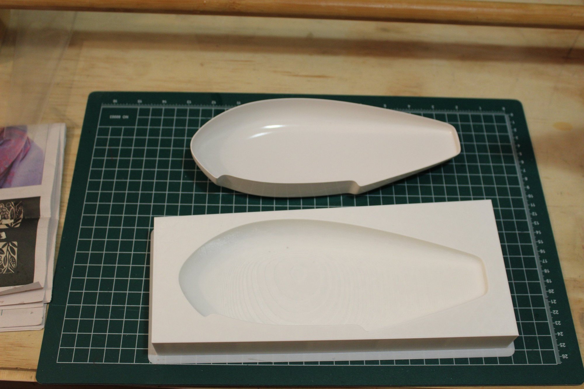
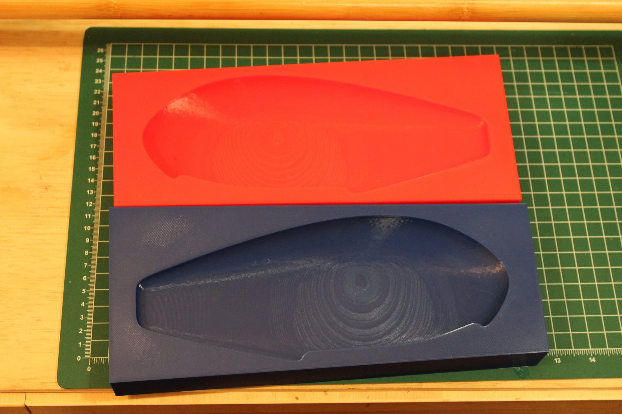
Also at the moment I am not planning to fit the aeroplane with spats, I decided to prepare 3D printed moulds for them (as no pair of the supplied ABS plastic spats actually fits together).
I scanned one ABS spat and created a mould design in Fusion 360 and had a test mould printed in draft mode. It turned out quite good.
Cheers,
Eran
I scanned one ABS spat and created a mould design in Fusion 360 and had a test mould printed in draft mode. It turned out quite good.
Cheers,
Eran
03-12-2024, 02:17 PM
#96
Thread Starter
Join Date: Jun 2008
Location: Perth WA, AUSTRALIA
Posts: 1,208
Likes: 0
Received 12 Likes
on
12 Posts
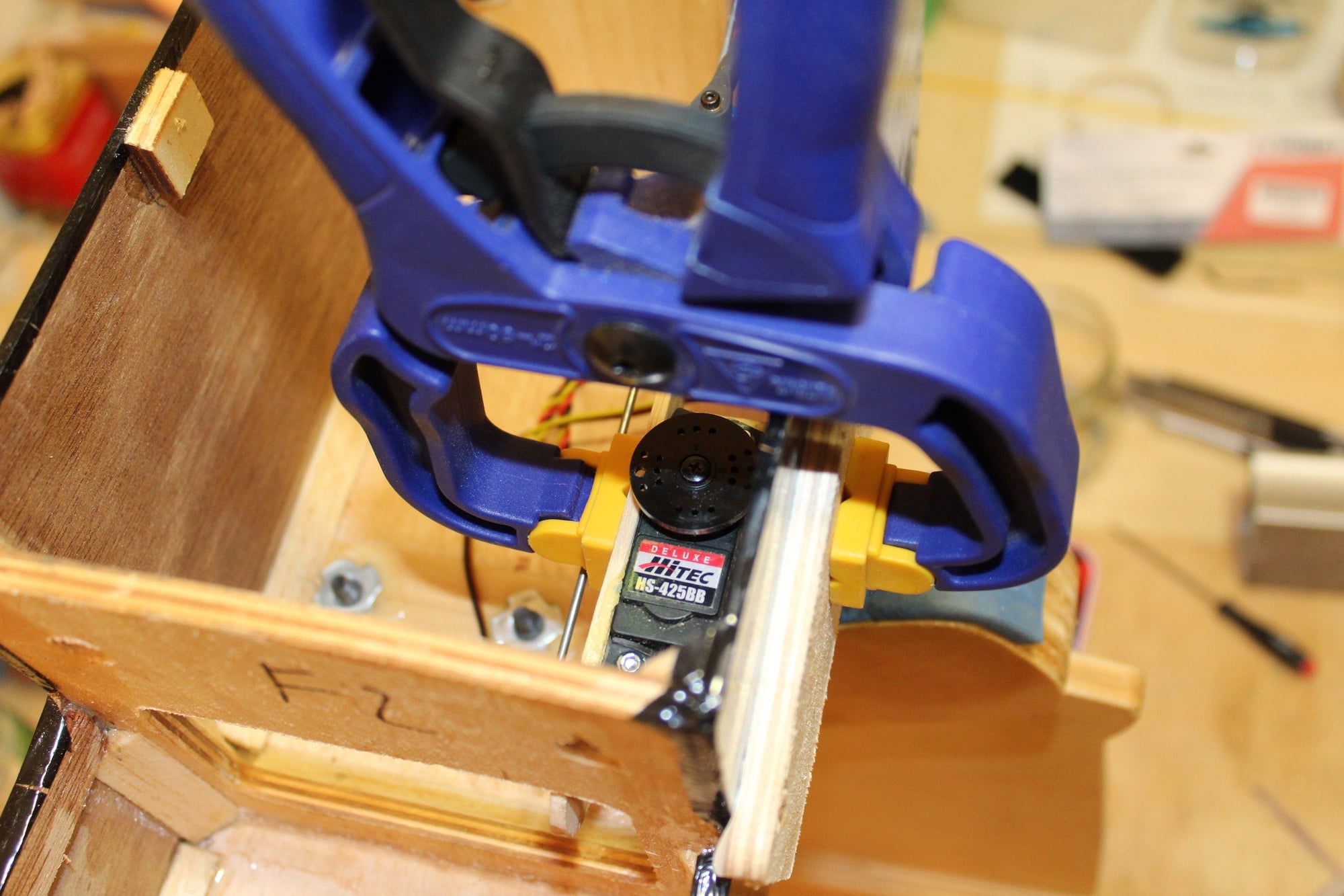
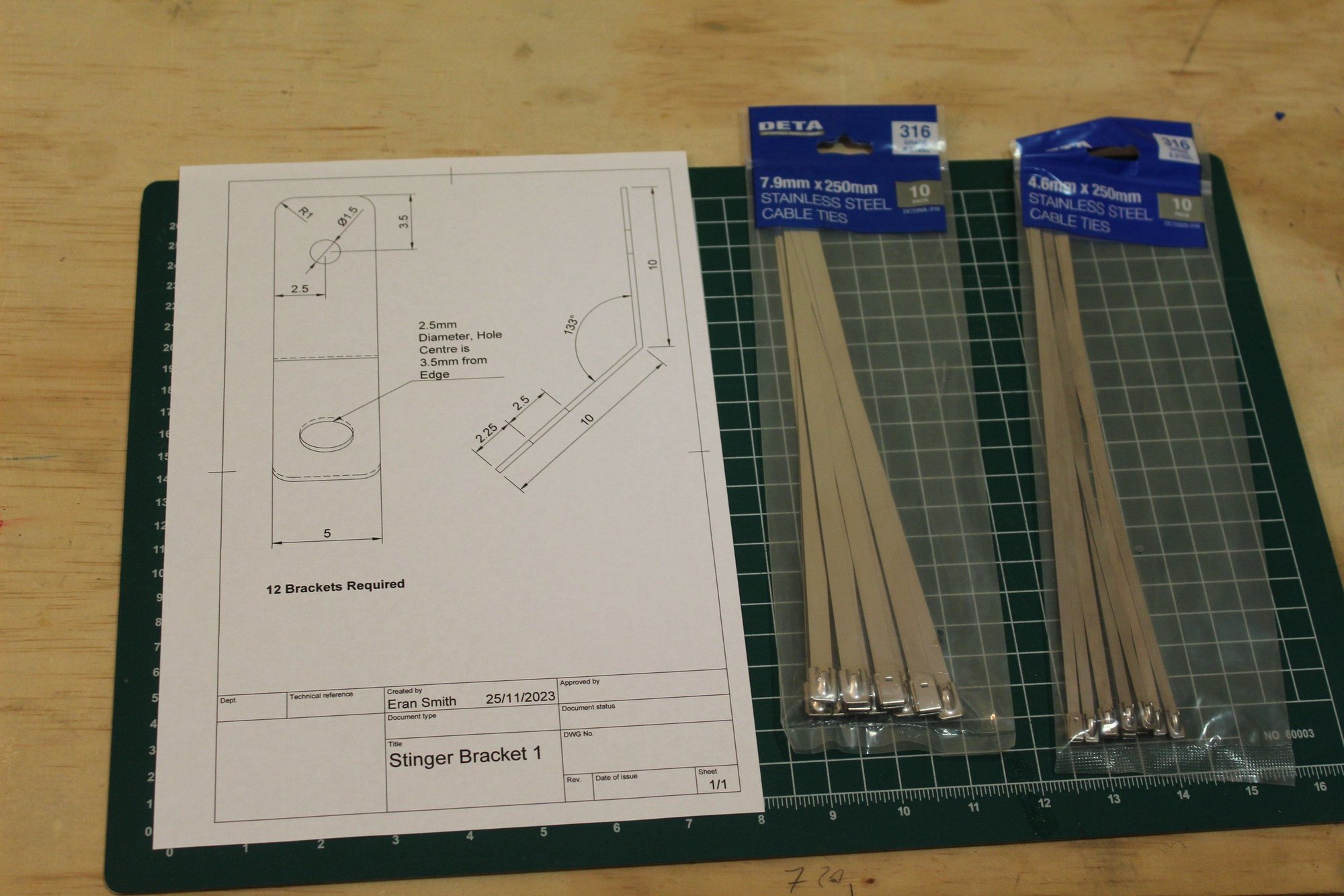
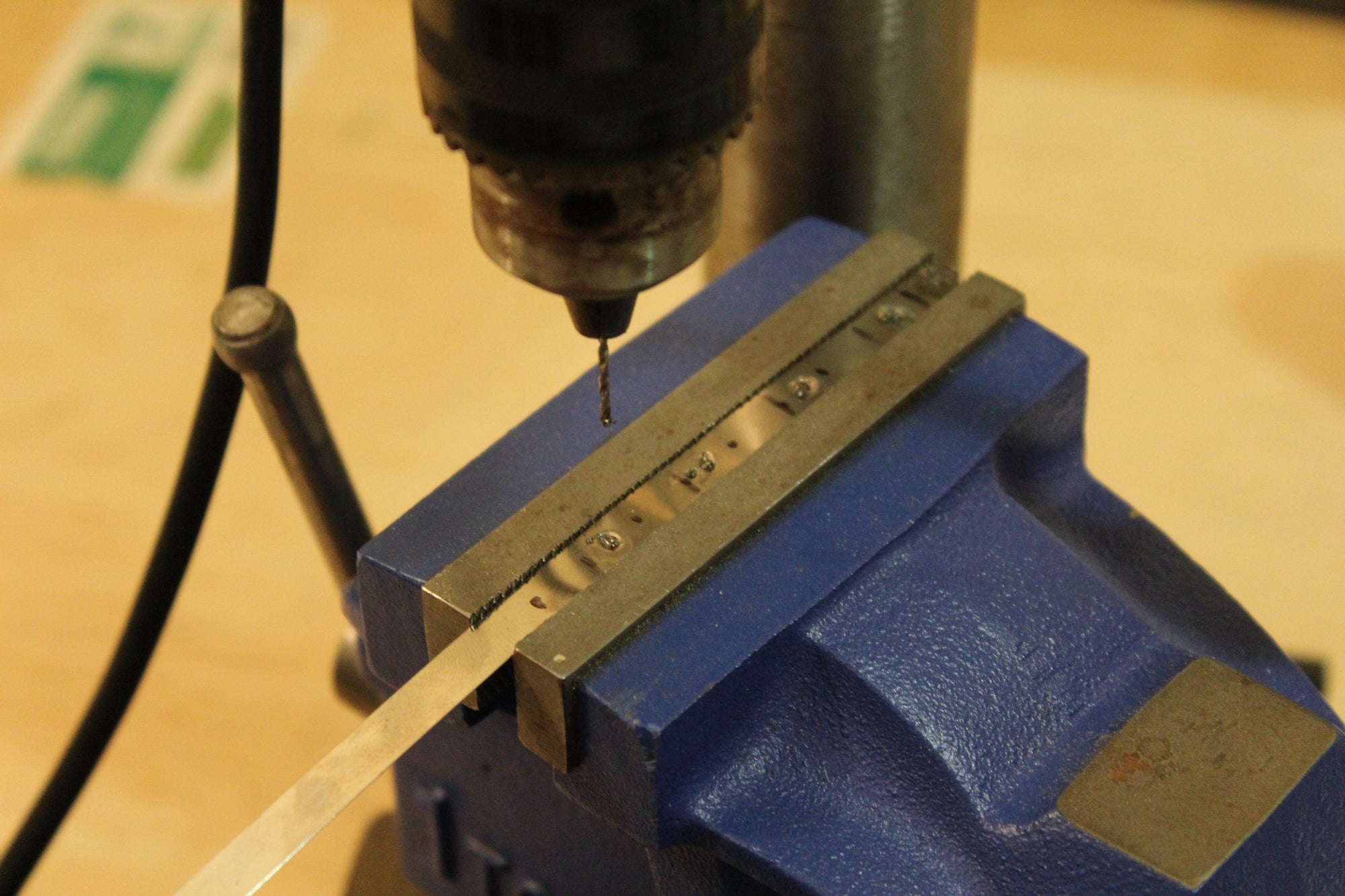
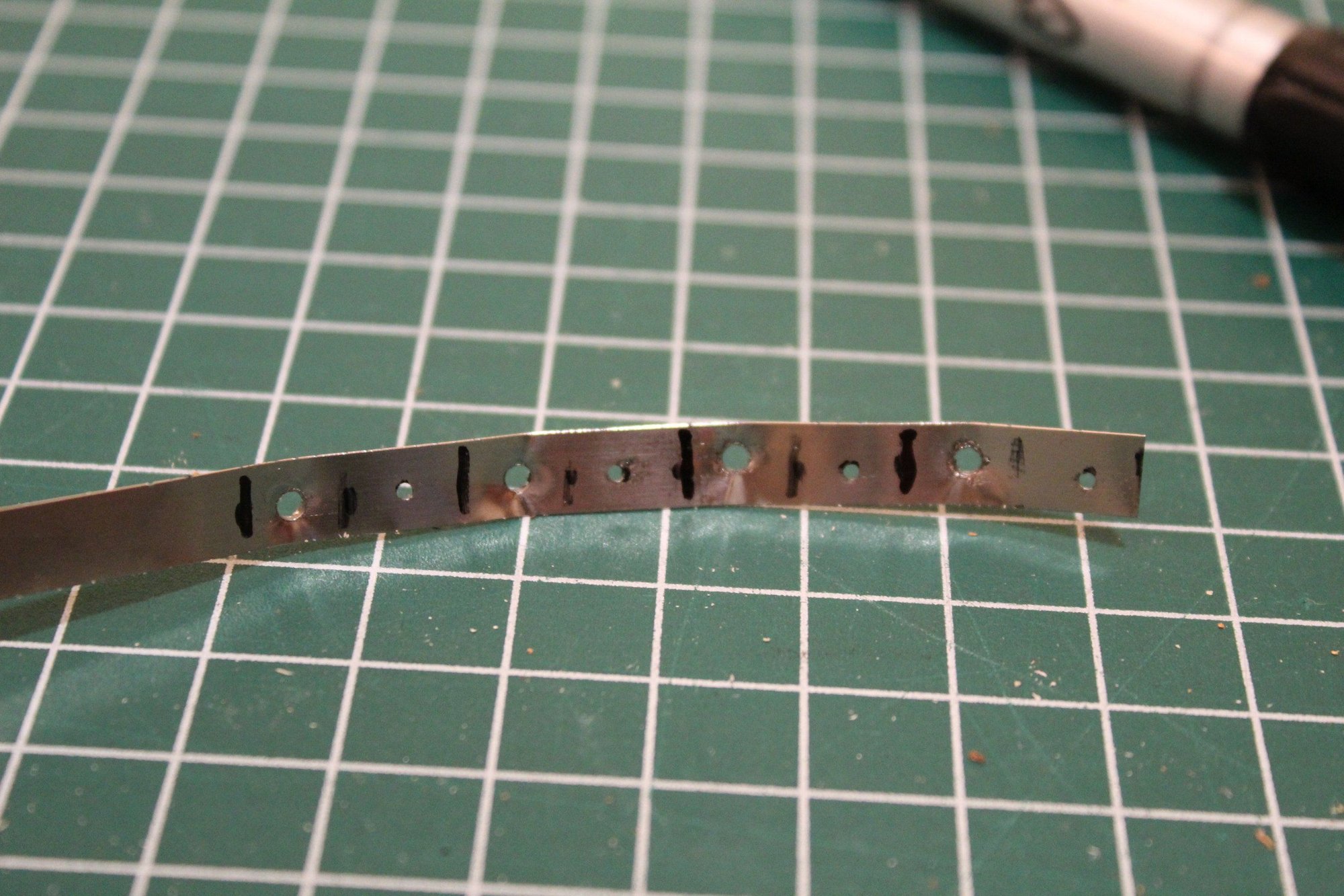
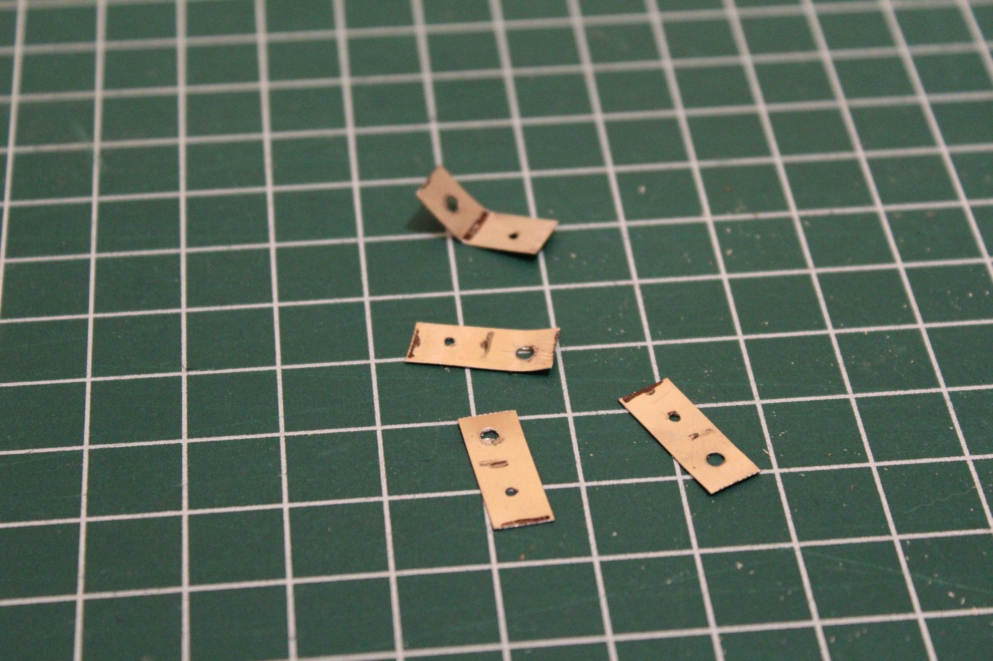
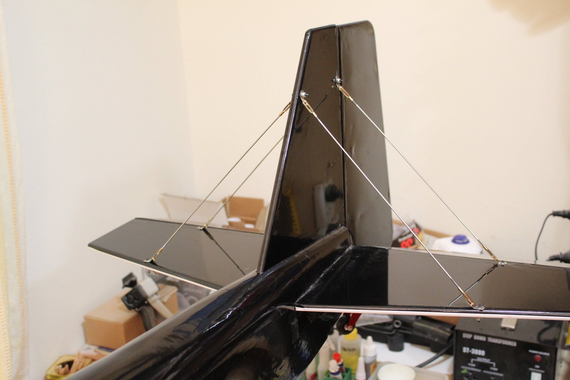
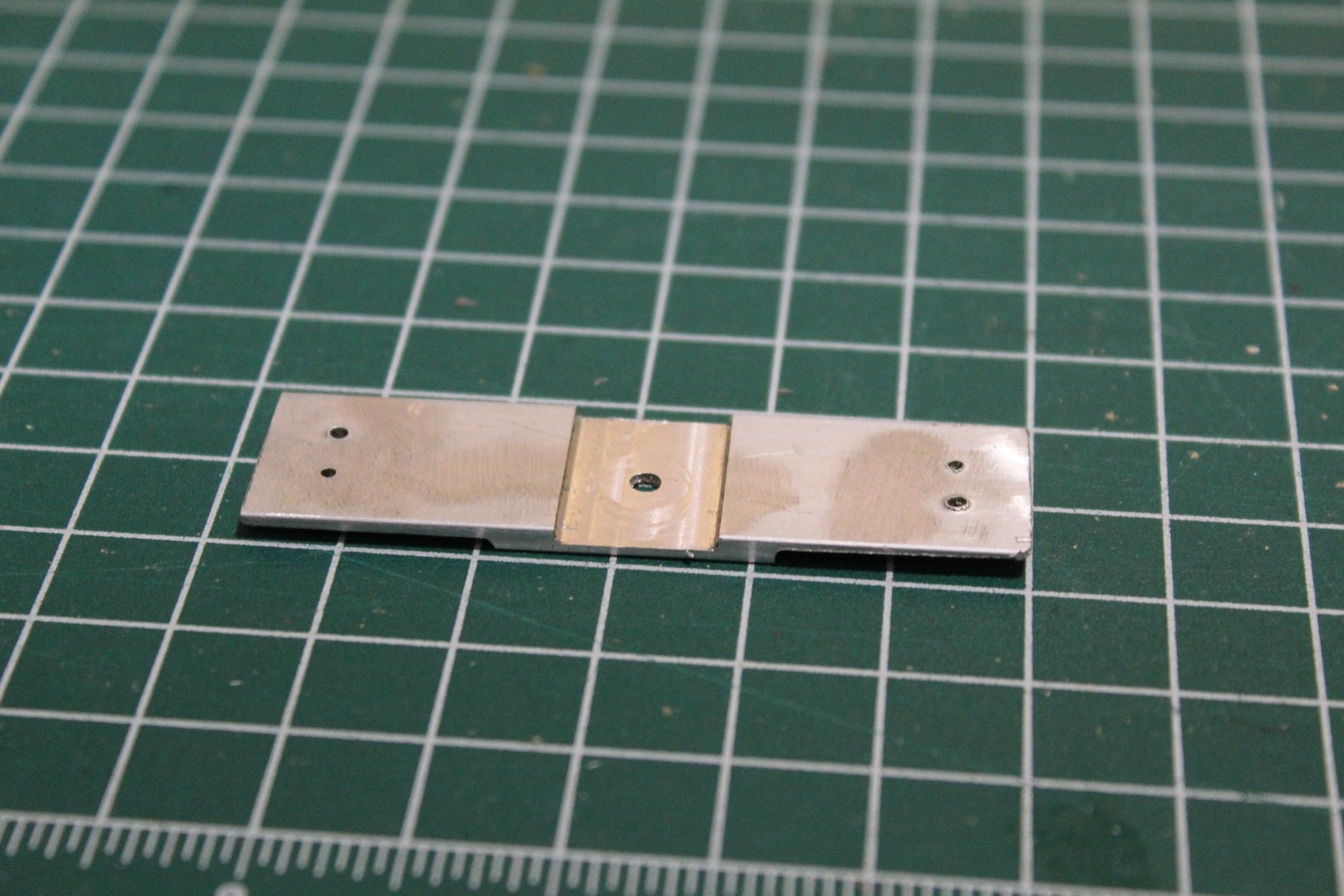
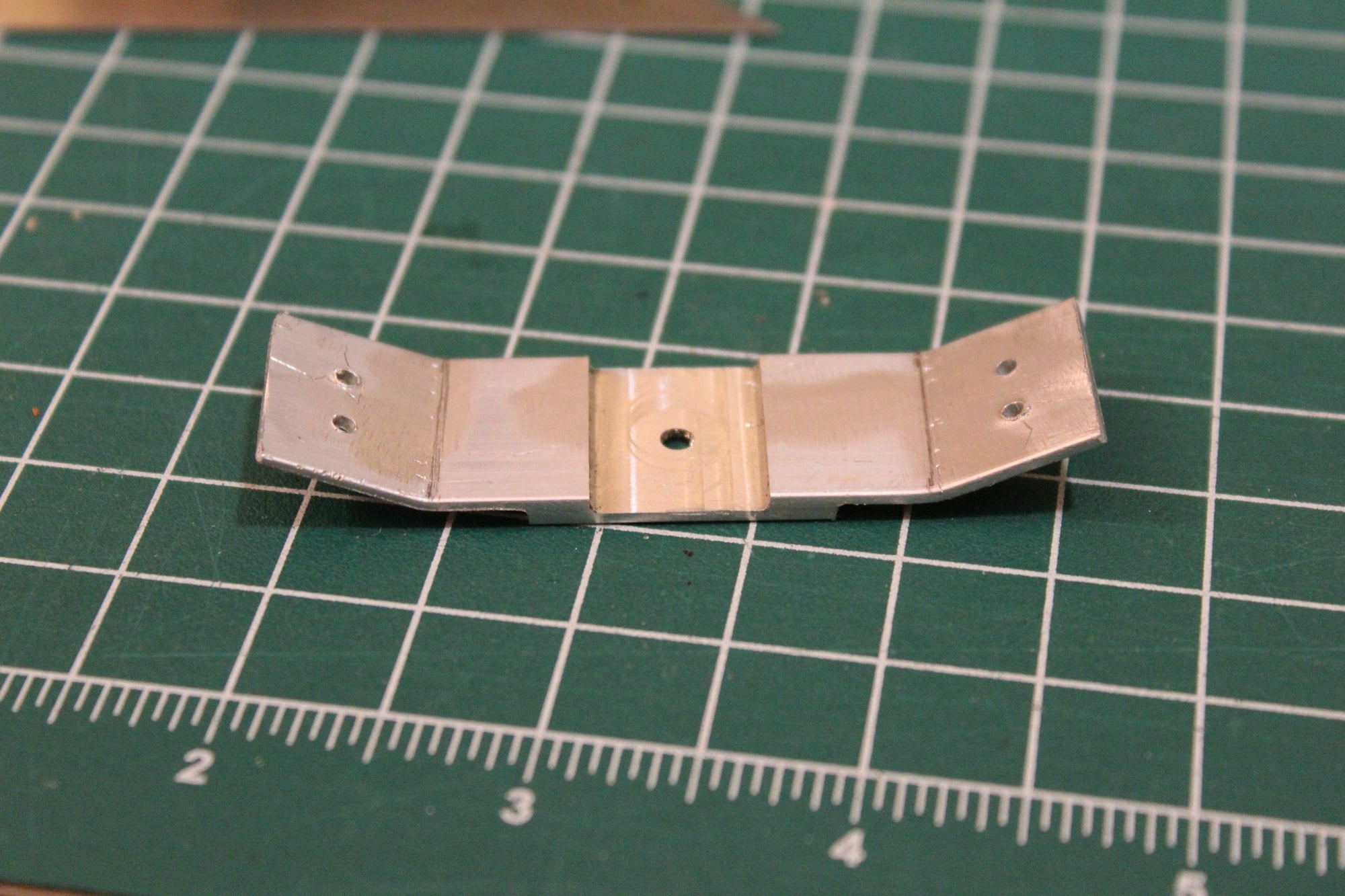
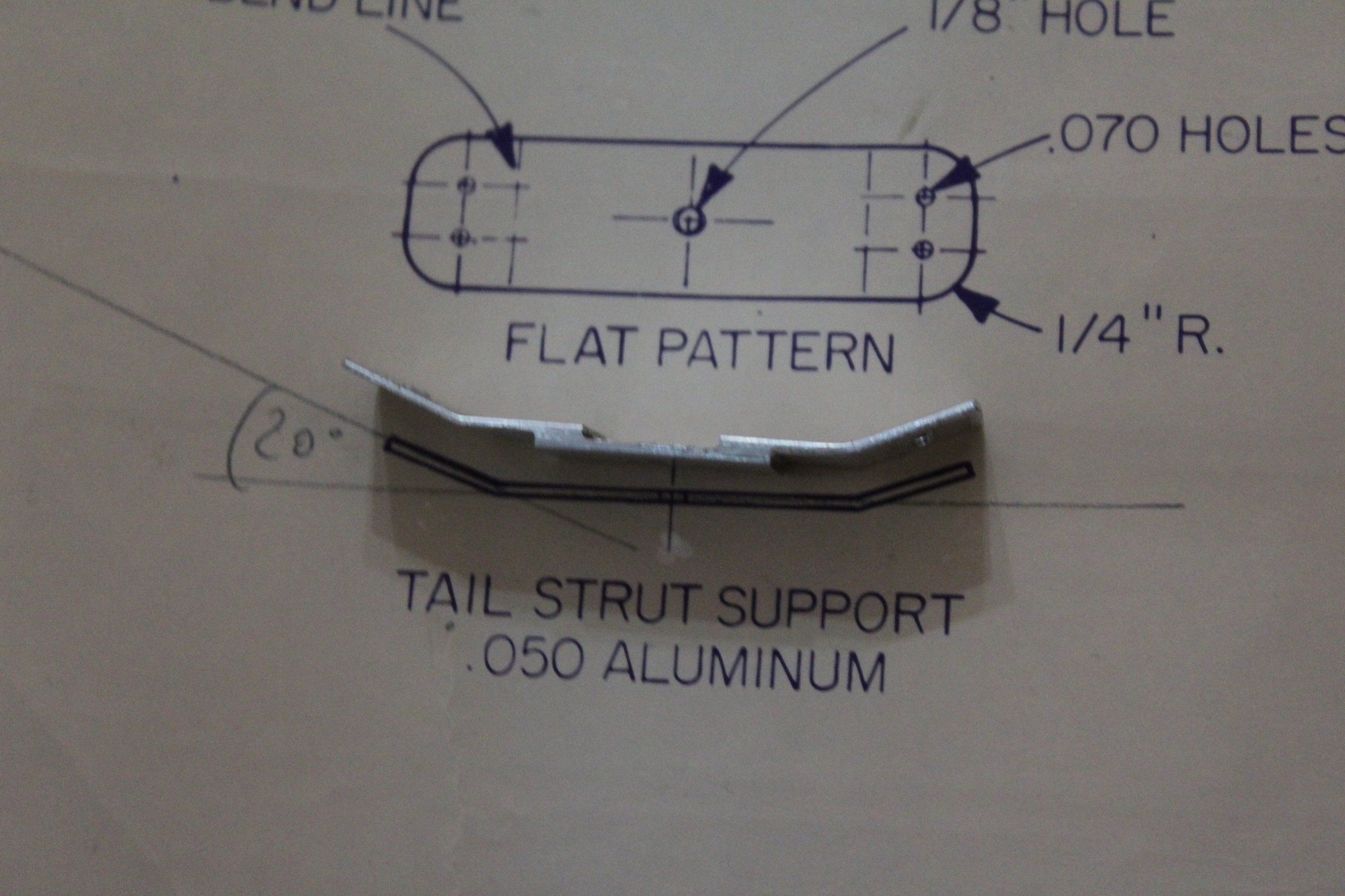
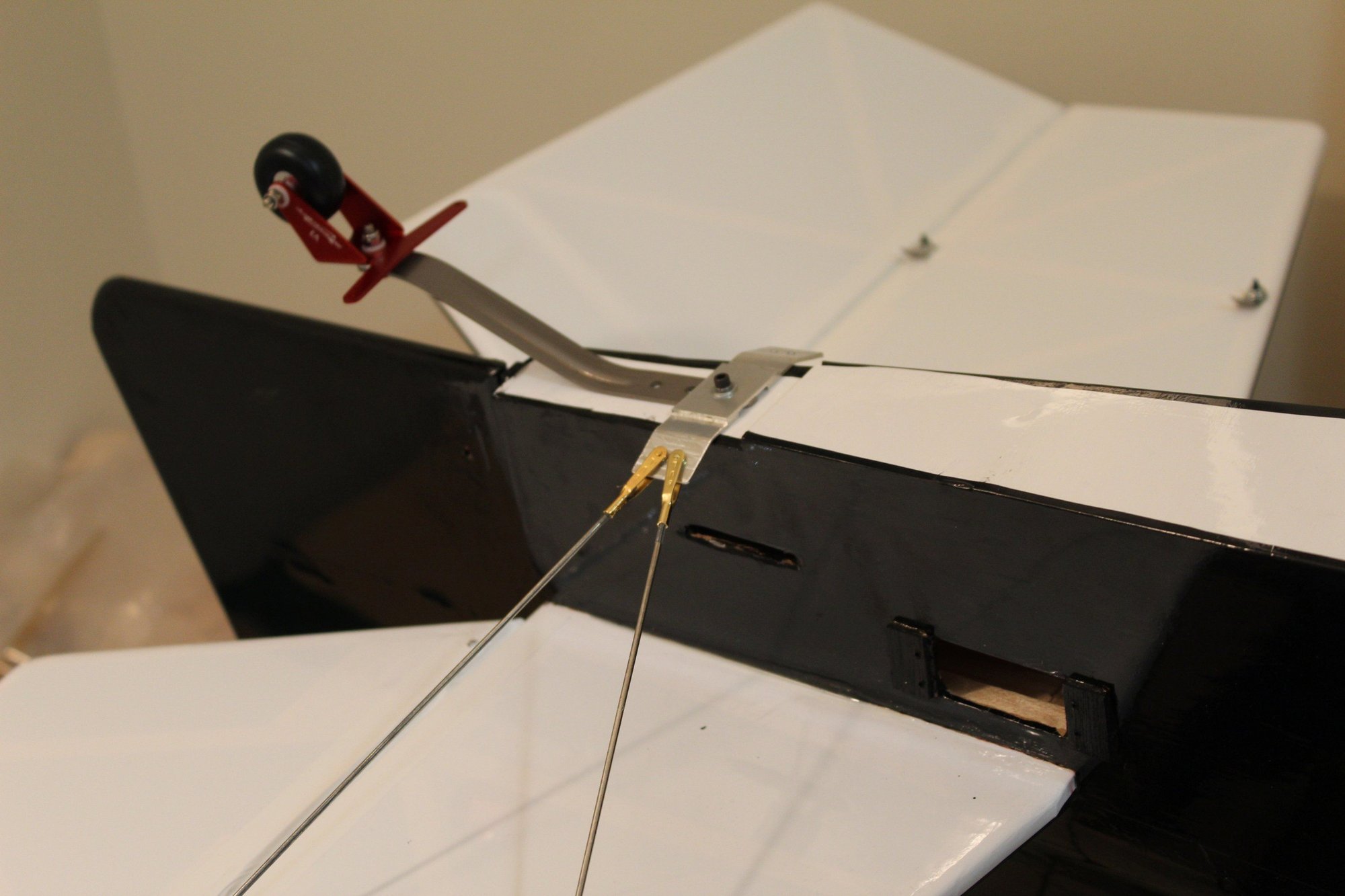
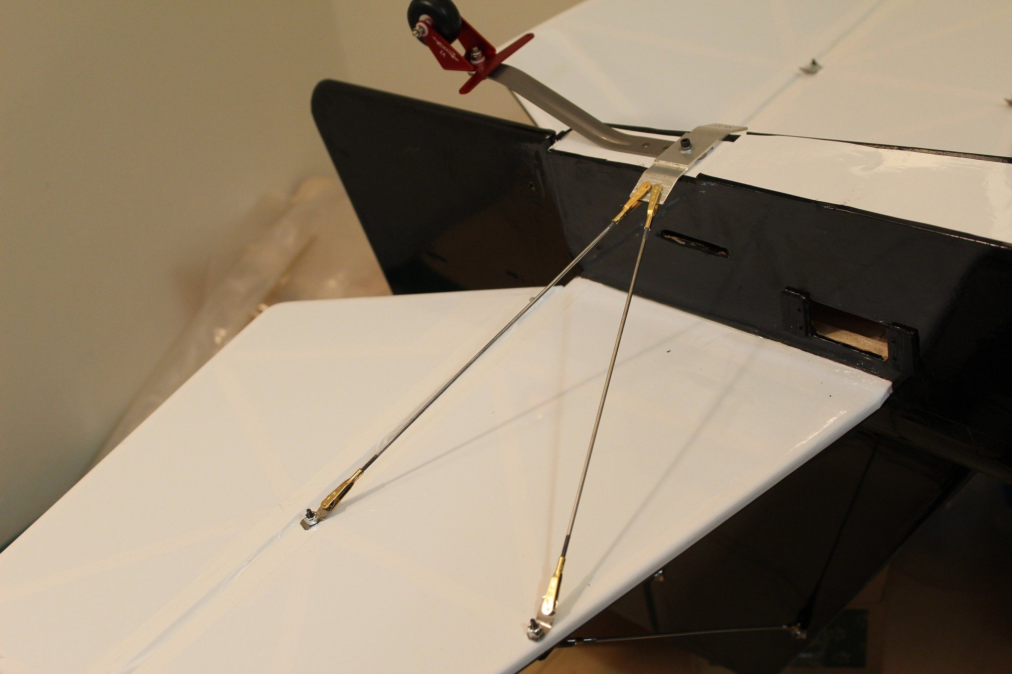
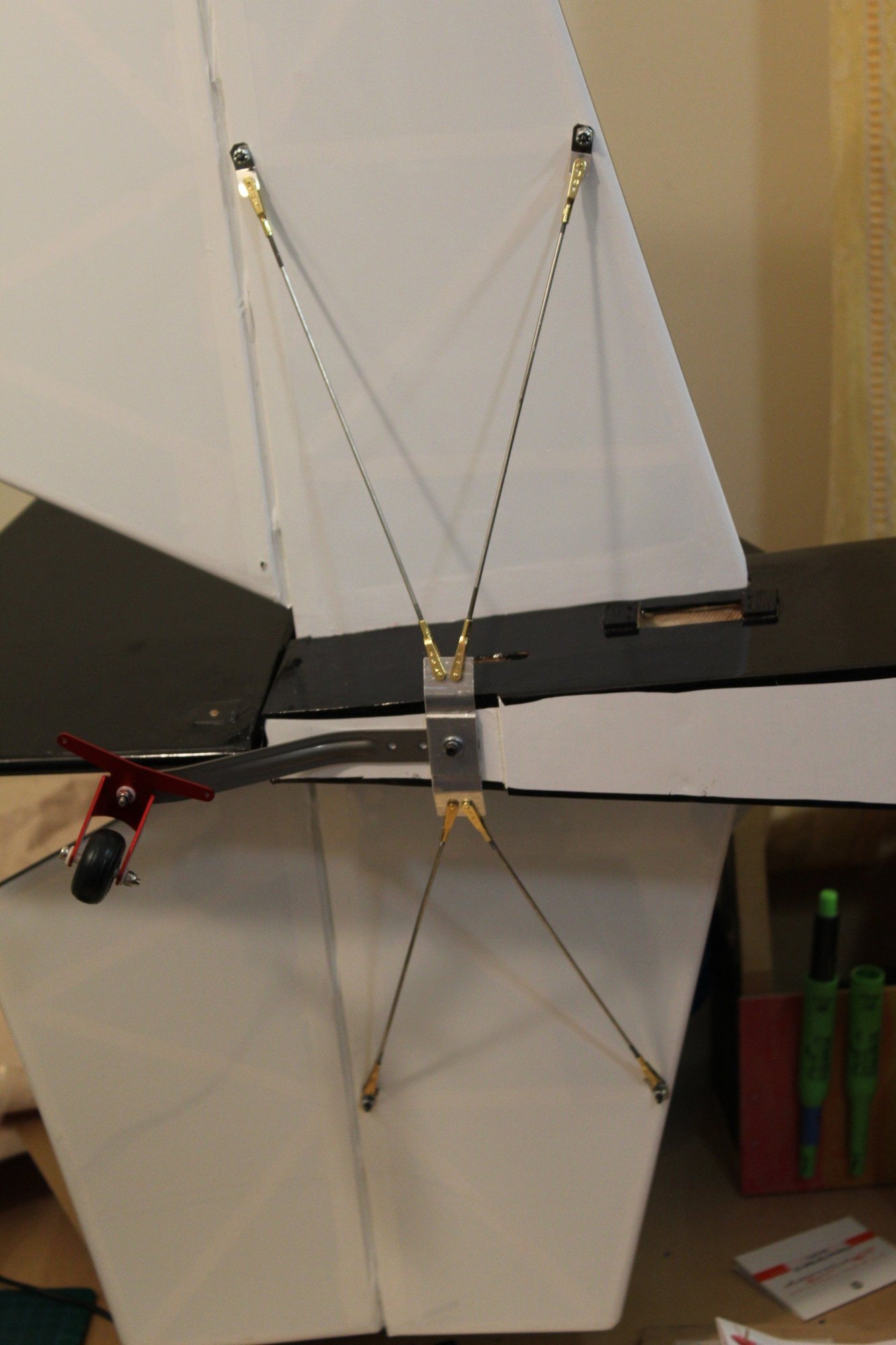
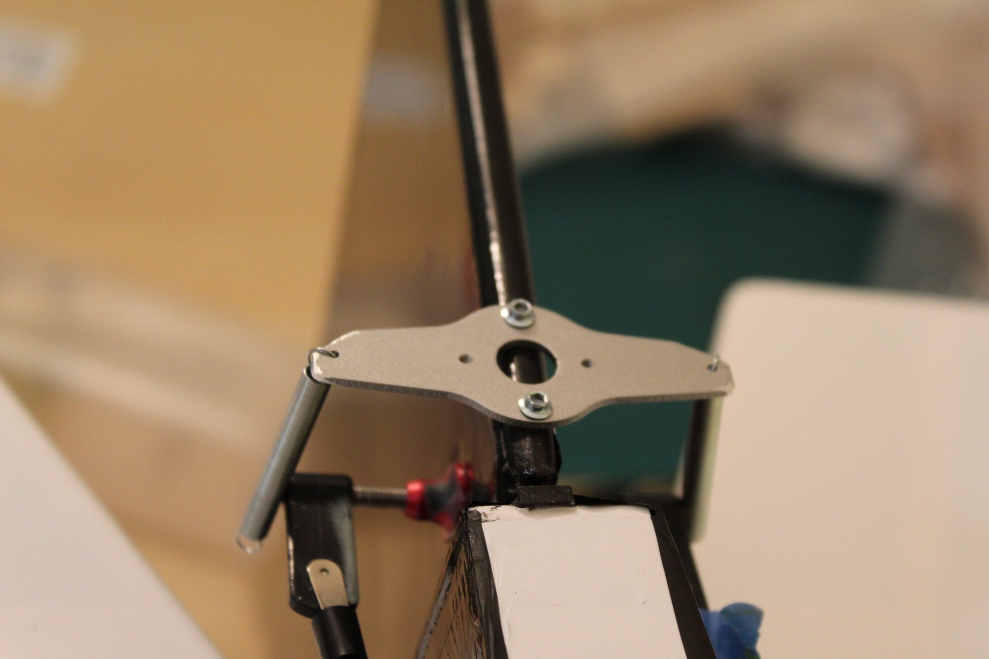
I fabricated the tail supports brackets from stainless steel cable ties. For the bracing supports I used the Great Planes 2-56 rods. Not like other rods currently available, the Great Planes rods allow for threading the rod's other side (i.e. the rod is in the correct diameter to do so). I used the 2-56 Sullivan's Gold-N-Clevis which is my personal preferred 2-56 clevises.
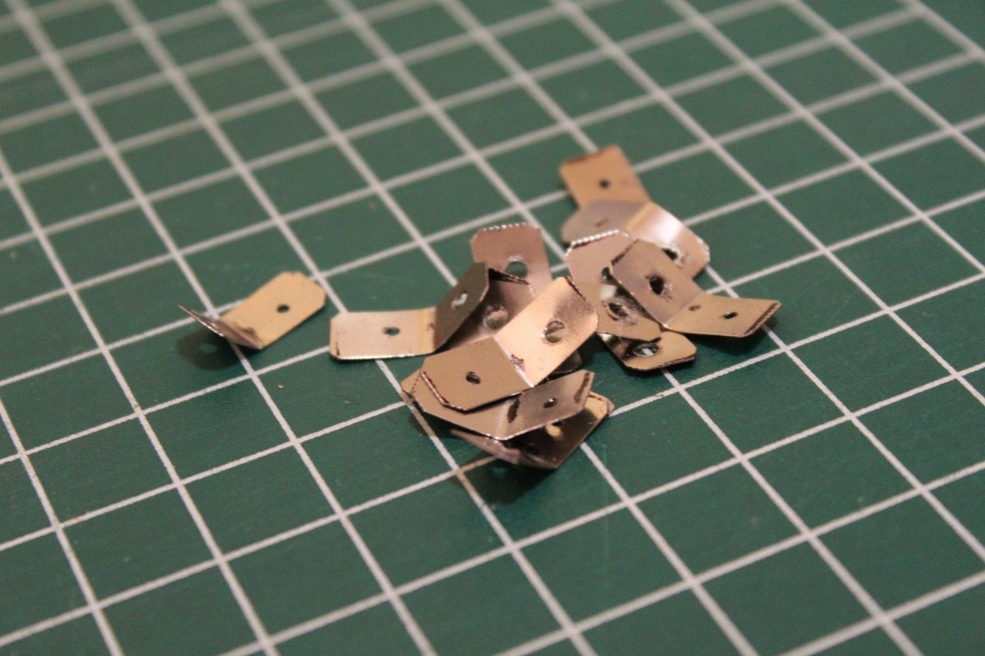

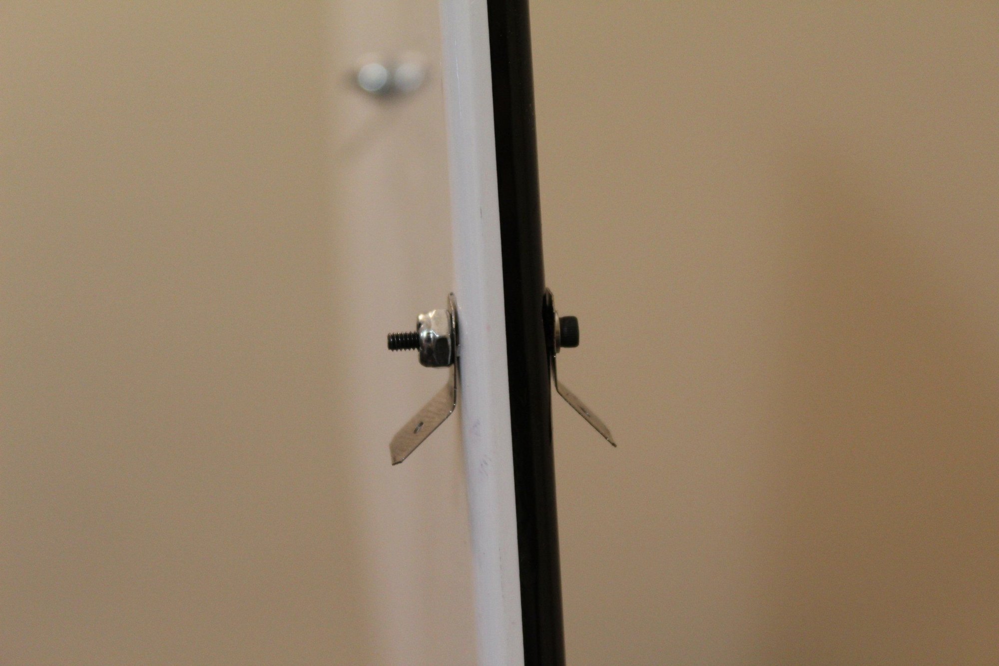
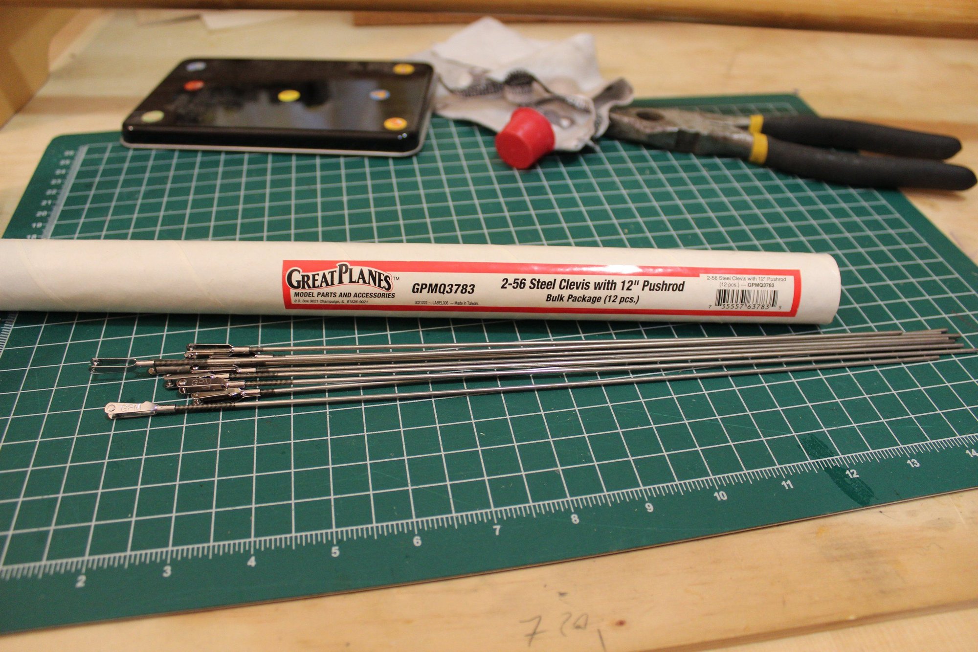
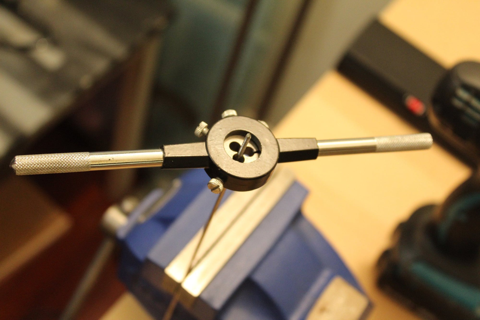
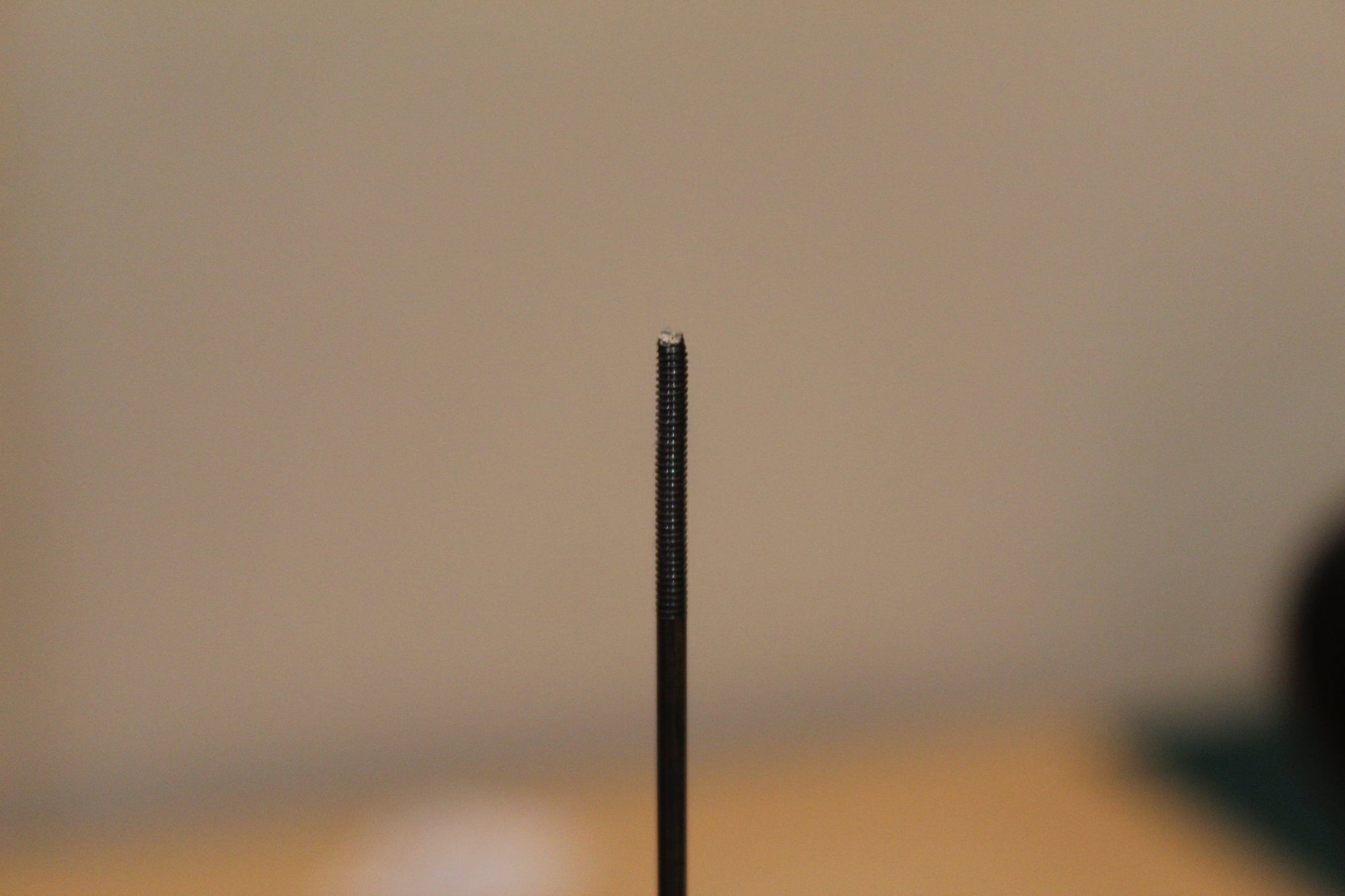
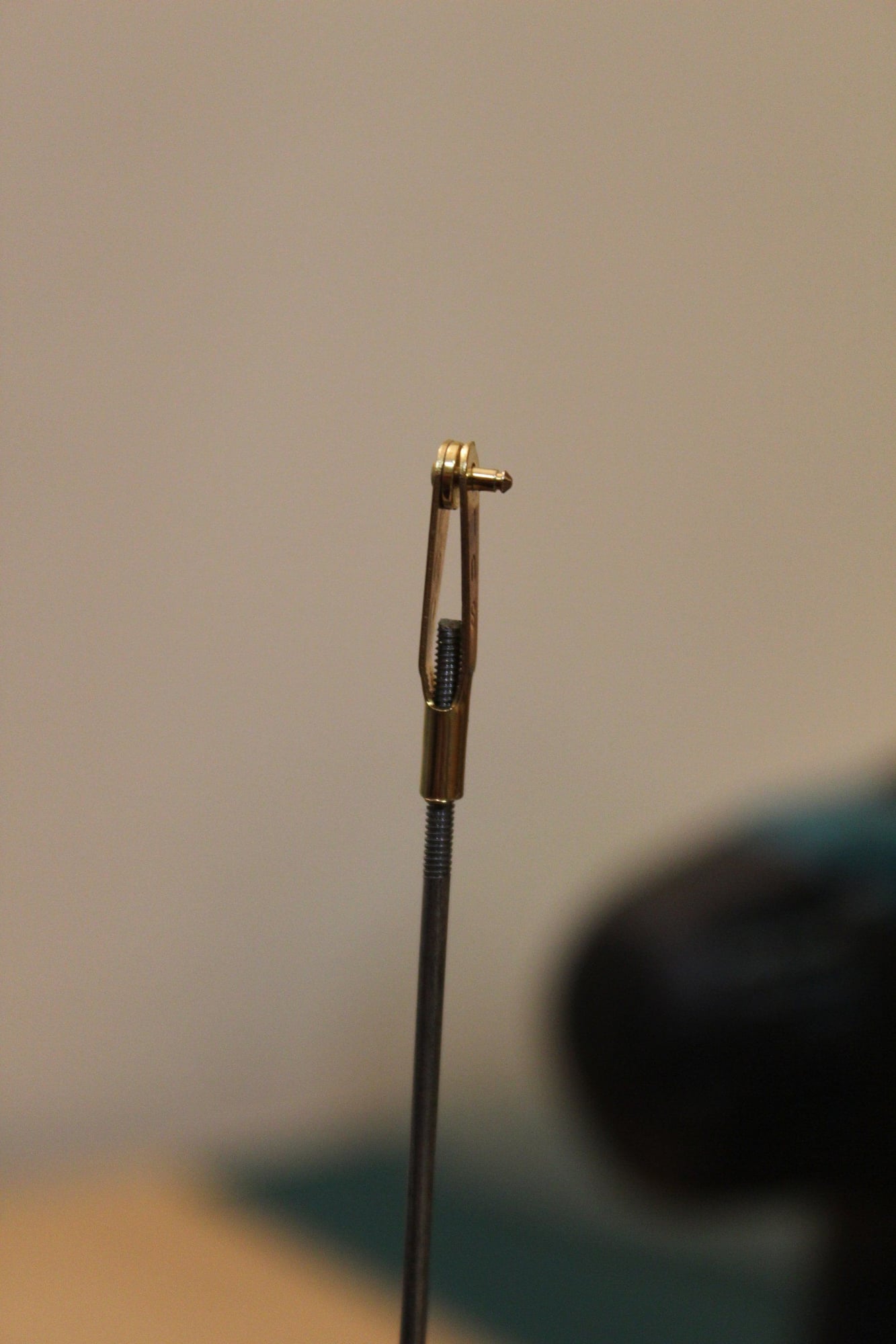
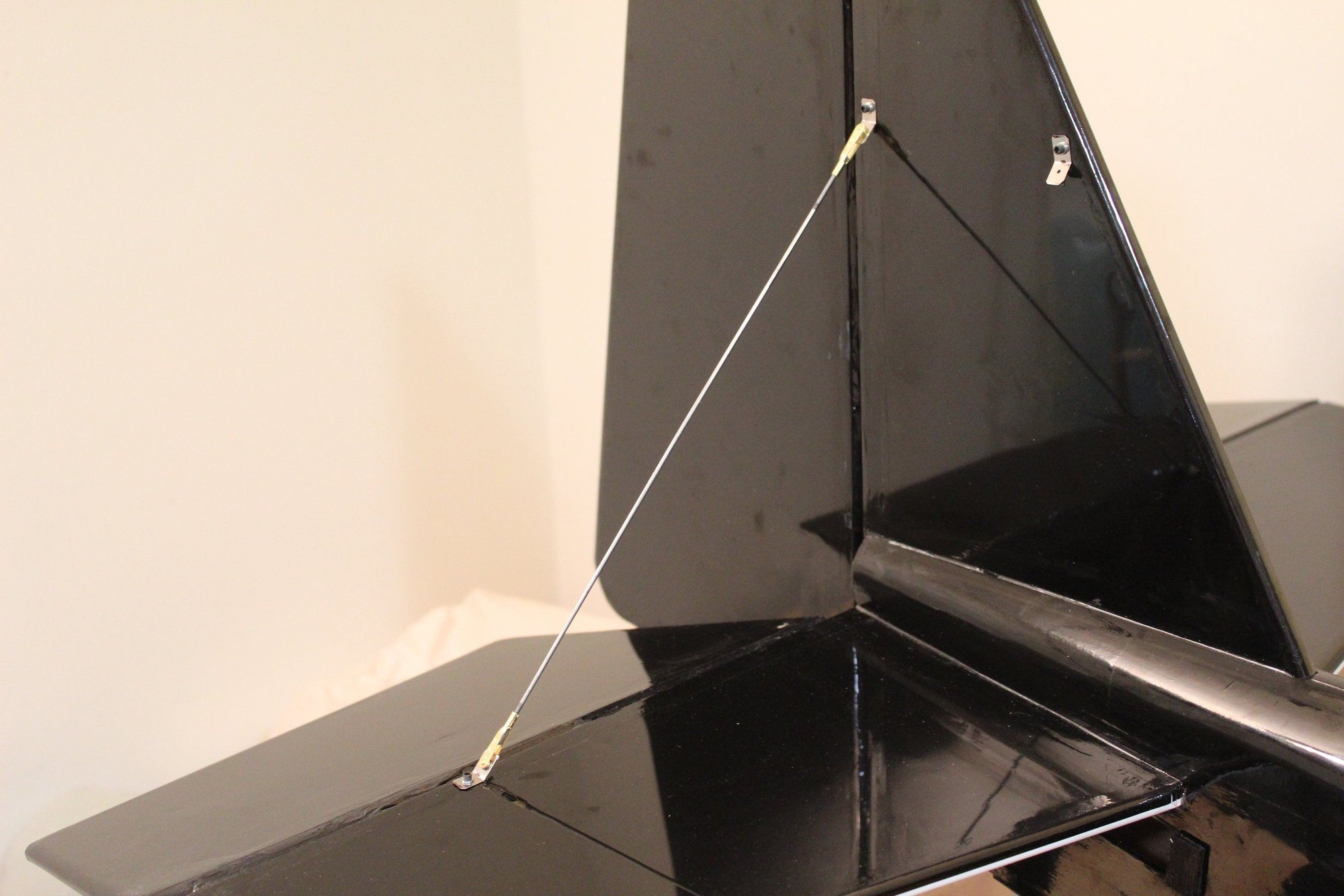

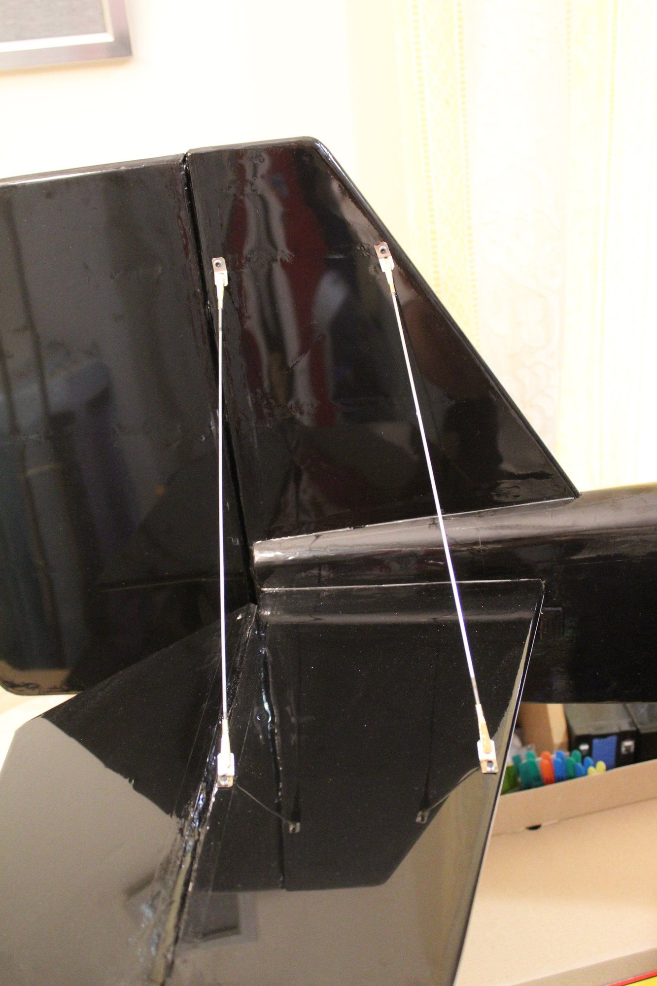
Cheers,
Eran
Cheers,
Eran
 03-15-2024, 03:32 AM
#98
Thread Starter
Join Date: Jun 2008
Location: Perth WA, AUSTRALIA
Posts: 1,208
Likes: 0
Received 12 Likes
on
12 Posts
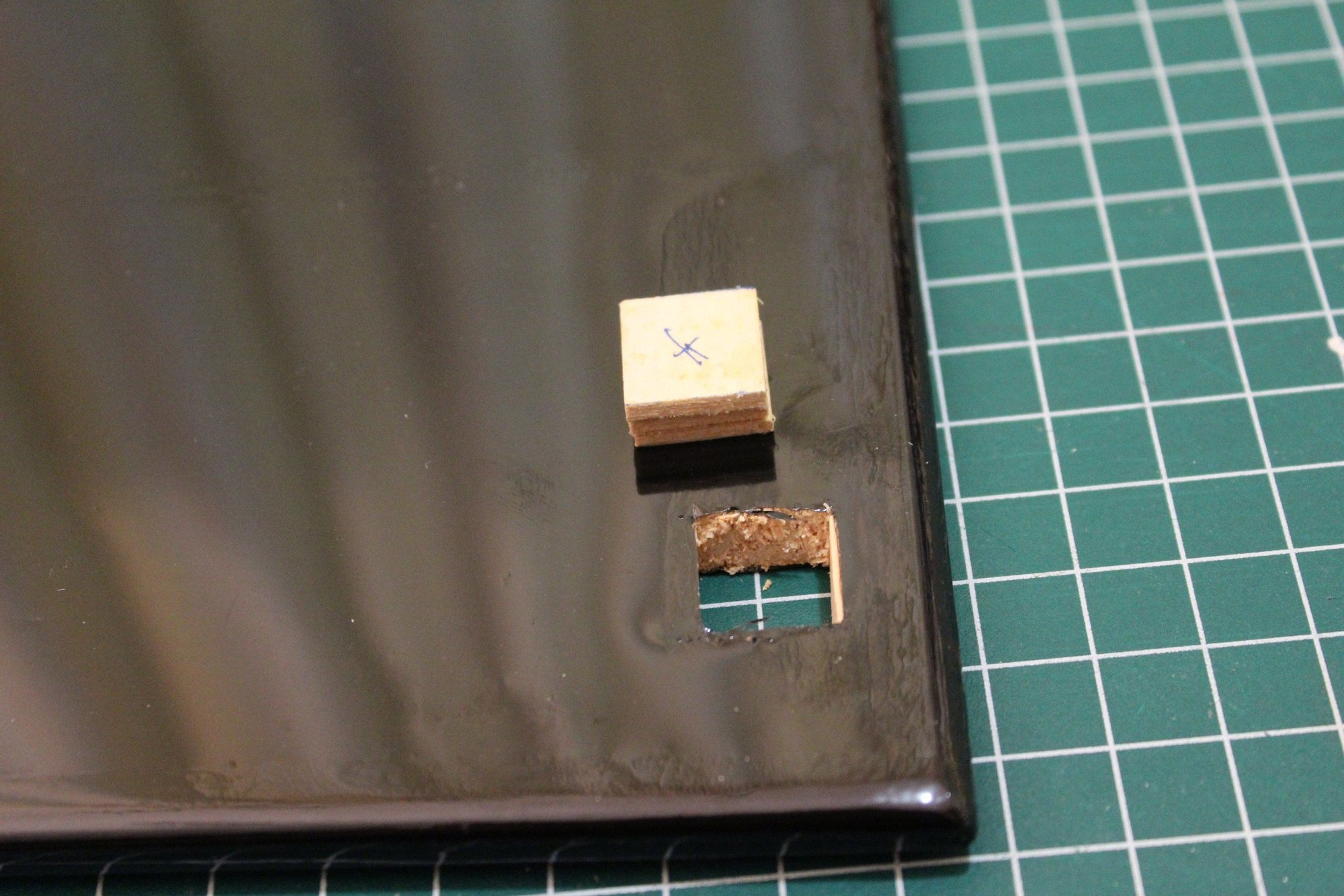
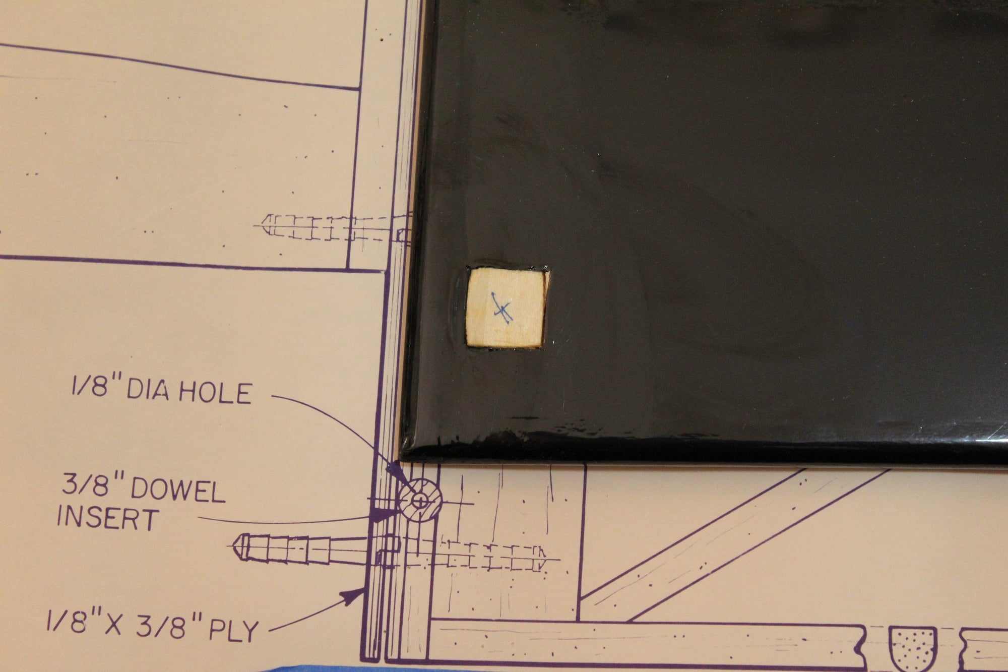
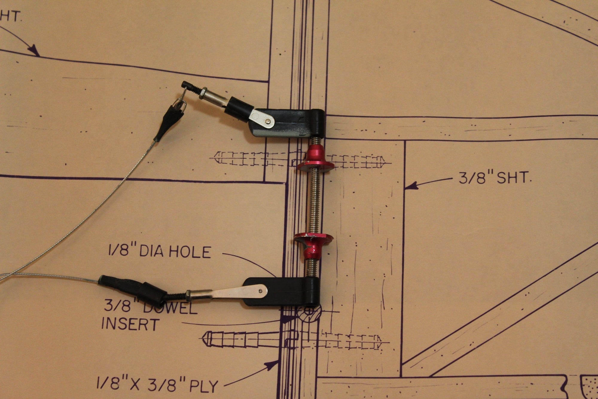
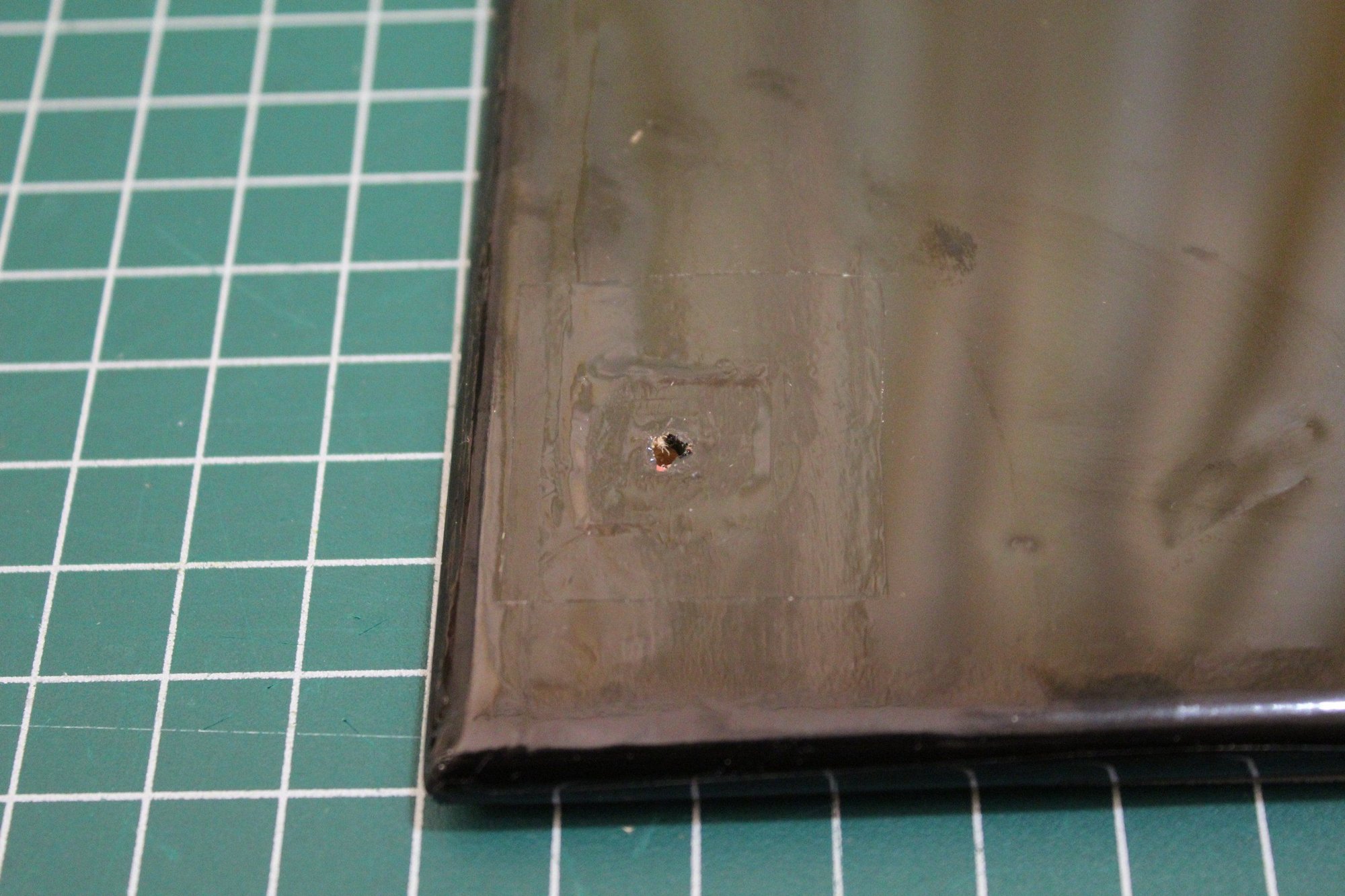
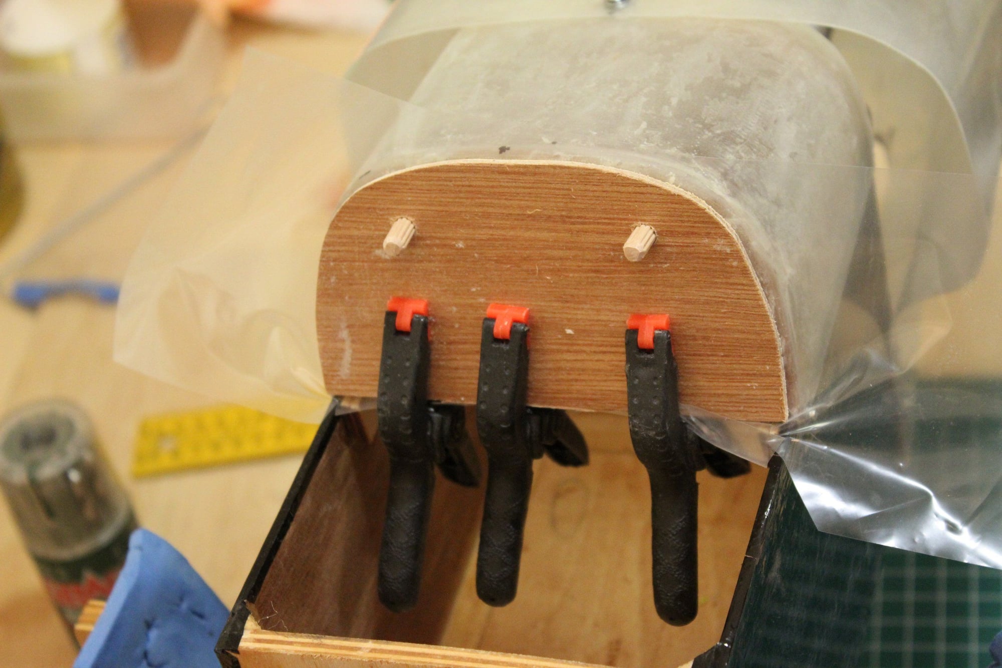
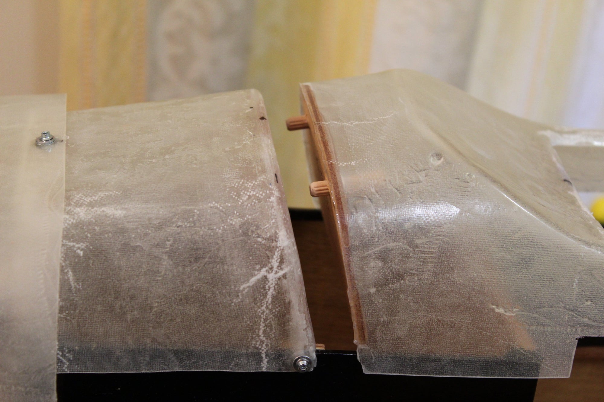
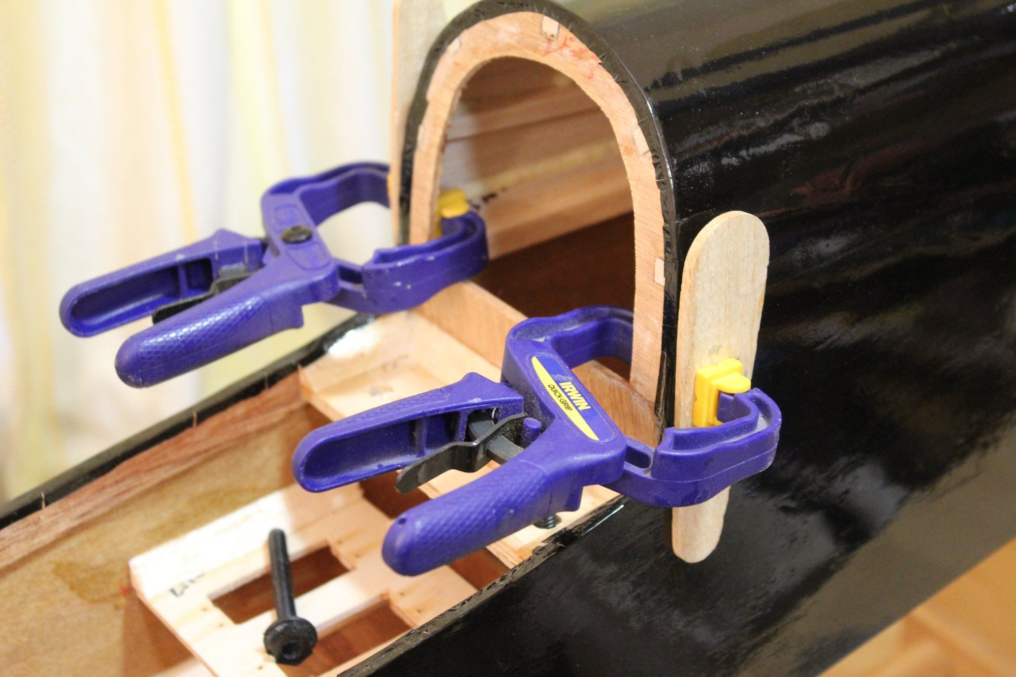
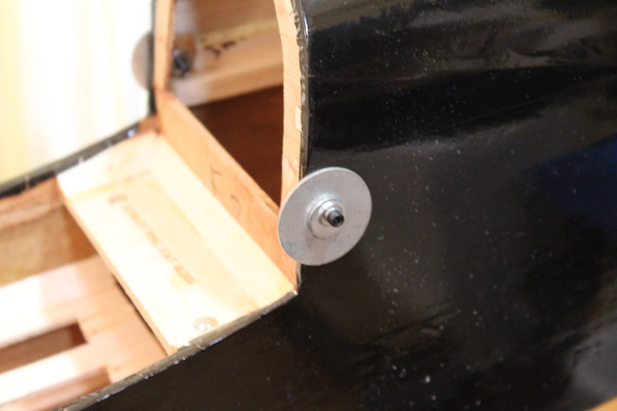
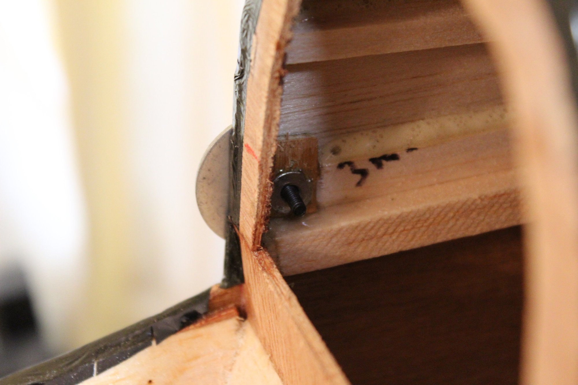
The dowels locking the front of the wing cover / cockpit section are glued into place. I then glued plywood blocks as doublers for lock-nuts (to hold the 4-40 screws that will hold this part at the back). I was using large washers to spread the load of the screw pulling the lock-nut into the wood.
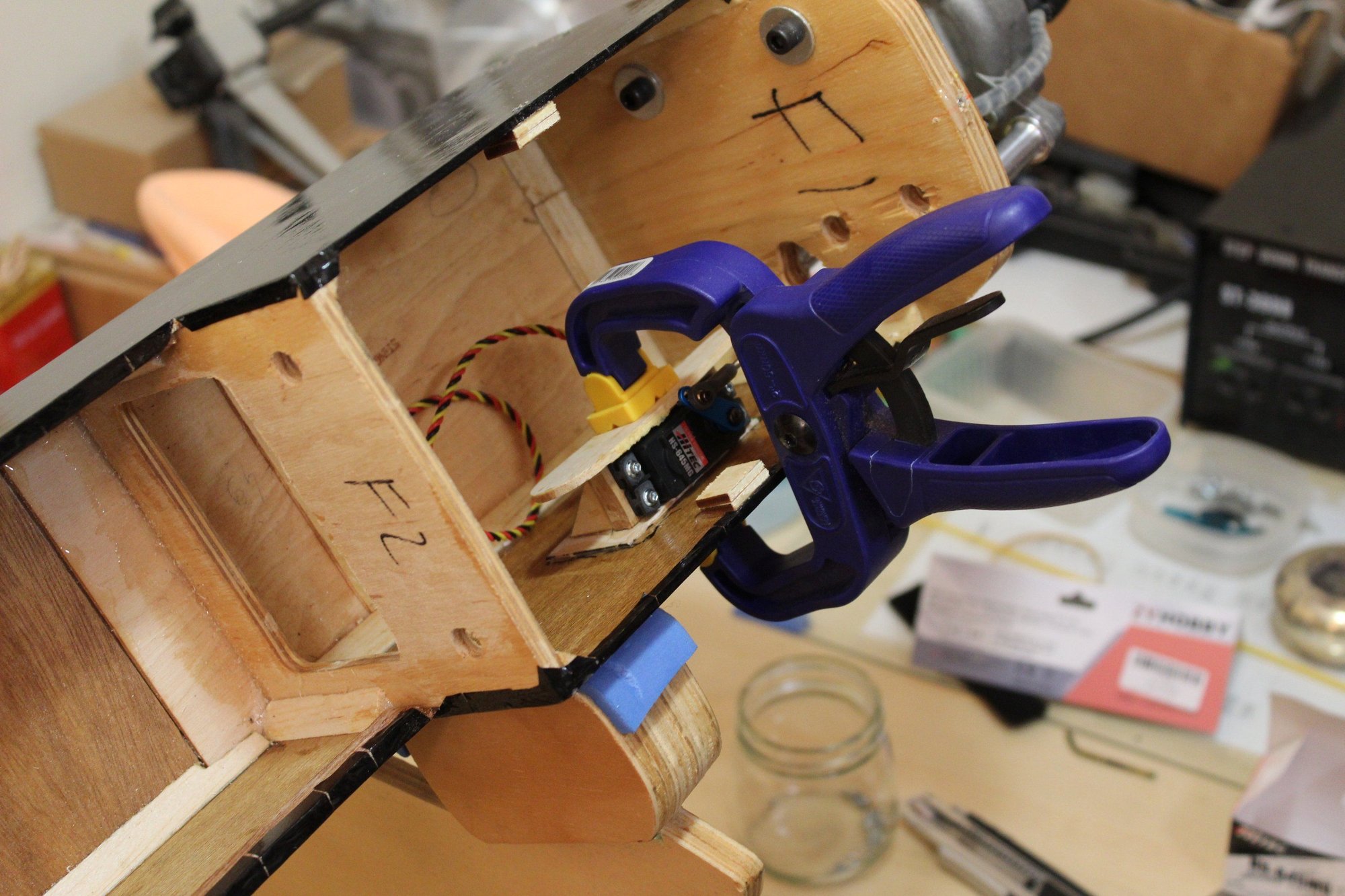
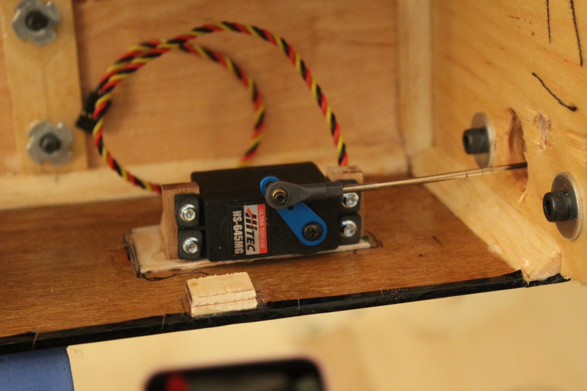
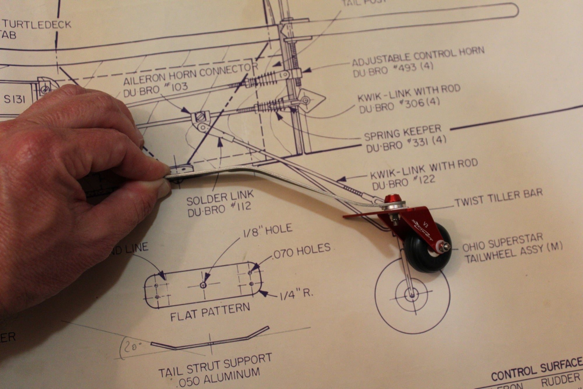
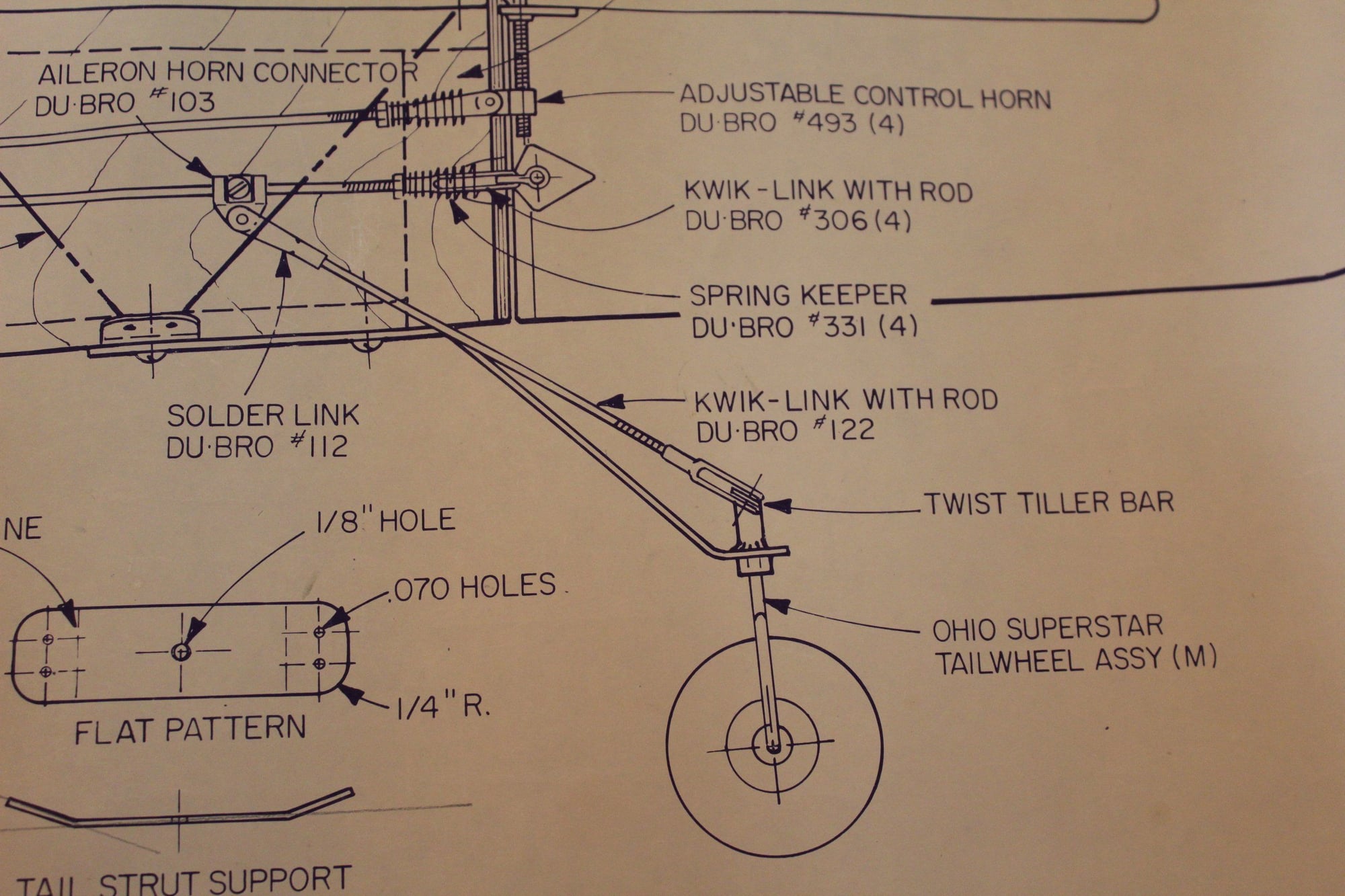
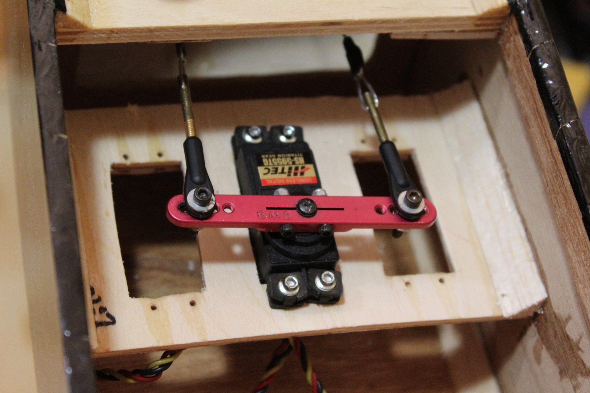
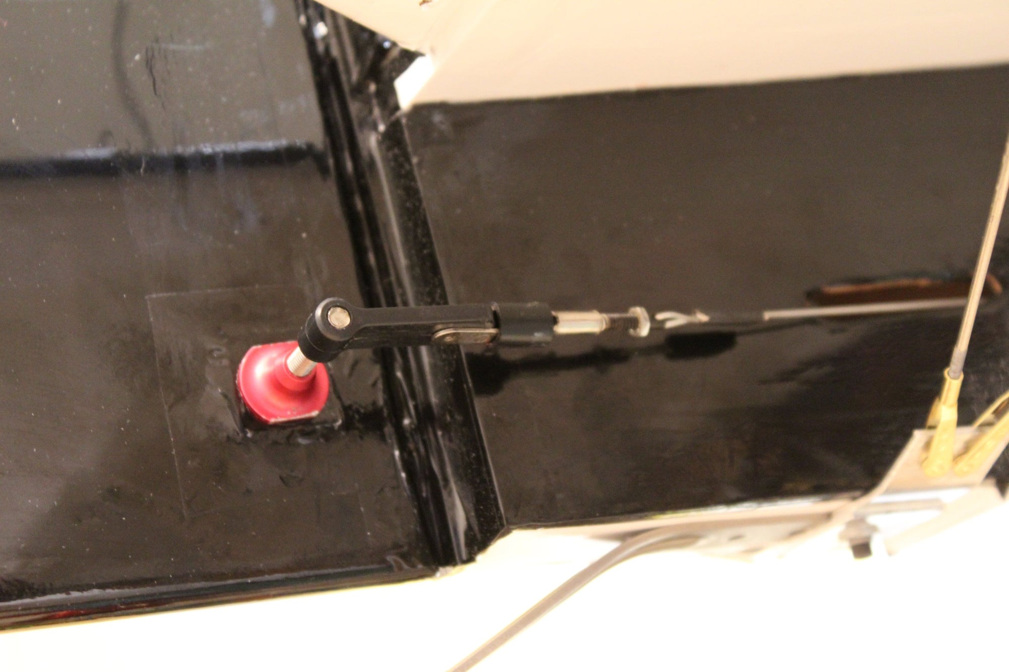
Next was fitting the rudder servo with the pull-pull cables and fitting the tail wheel. My friend also brought the moulds for the wheel pants 3D printed in high quality. I am not sure yet if I will bother with making the wheel pants.
Cheers,
Eran
Next was fitting the rudder servo with the pull-pull cables and fitting the tail wheel. My friend also brought the moulds for the wheel pants 3D printed in high quality. I am not sure yet if I will bother with making the wheel pants.
Cheers,
Eran
03-17-2024, 03:29 AM
#99
Thread Starter
Join Date: Jun 2008
Location: Perth WA, AUSTRALIA
Posts: 1,208
Likes: 0
Received 12 Likes
on
12 Posts
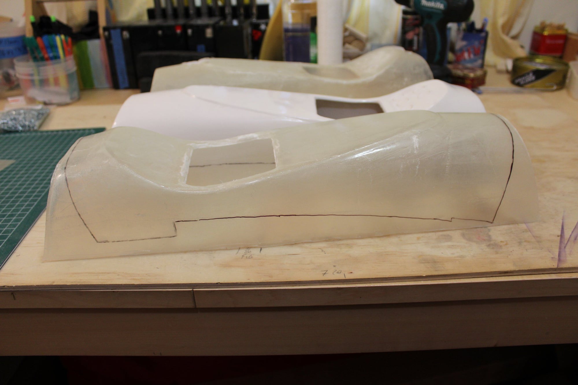
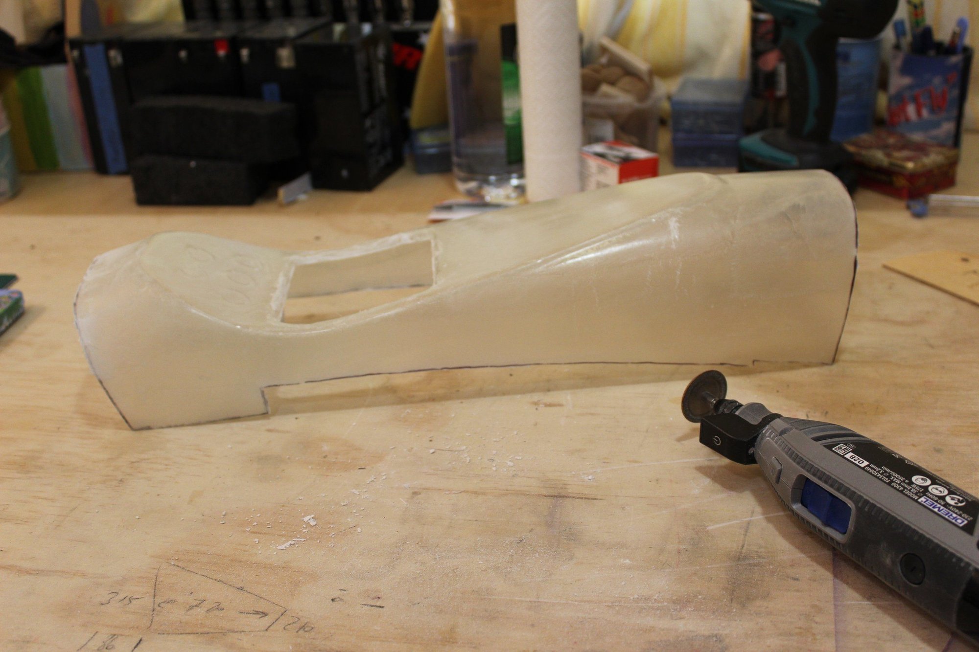
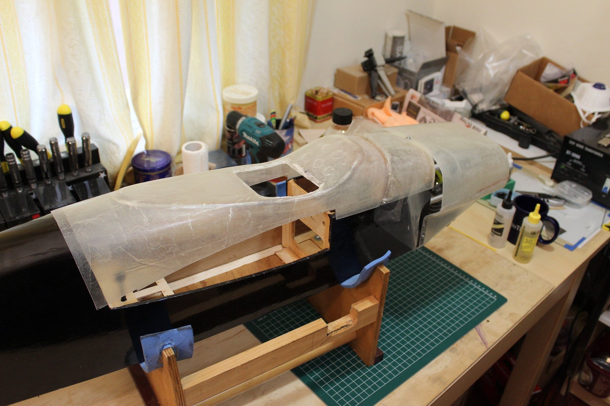
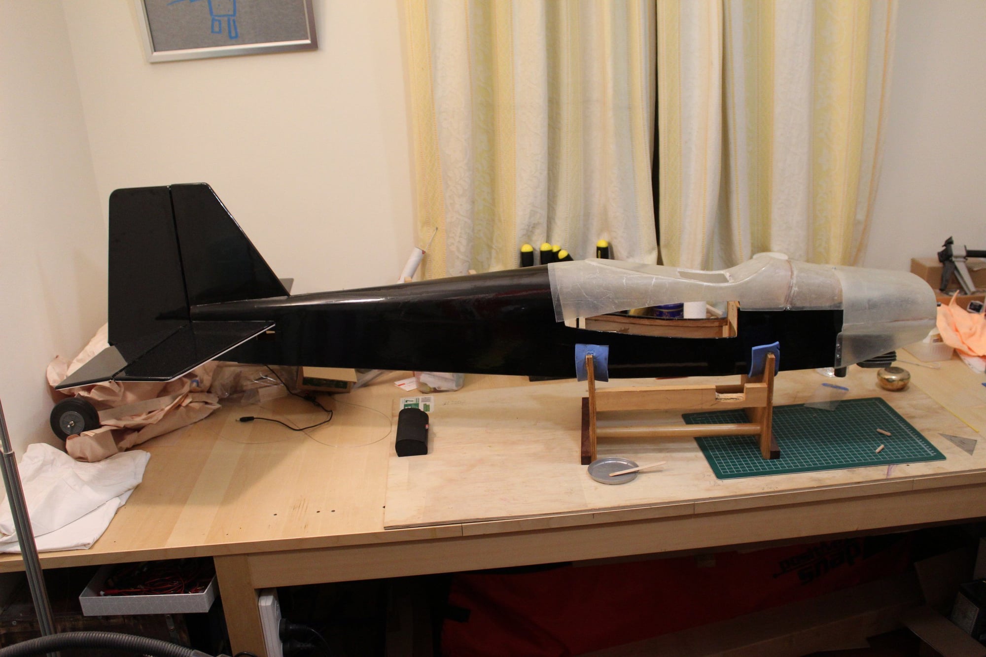
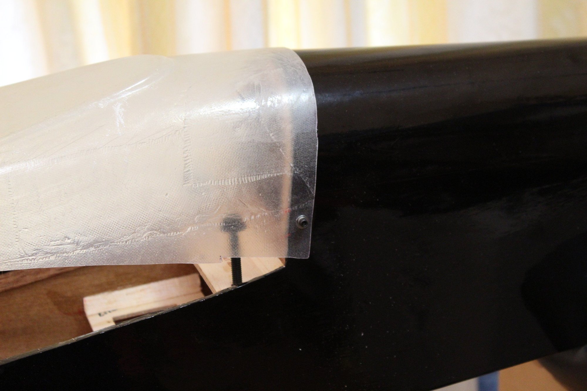
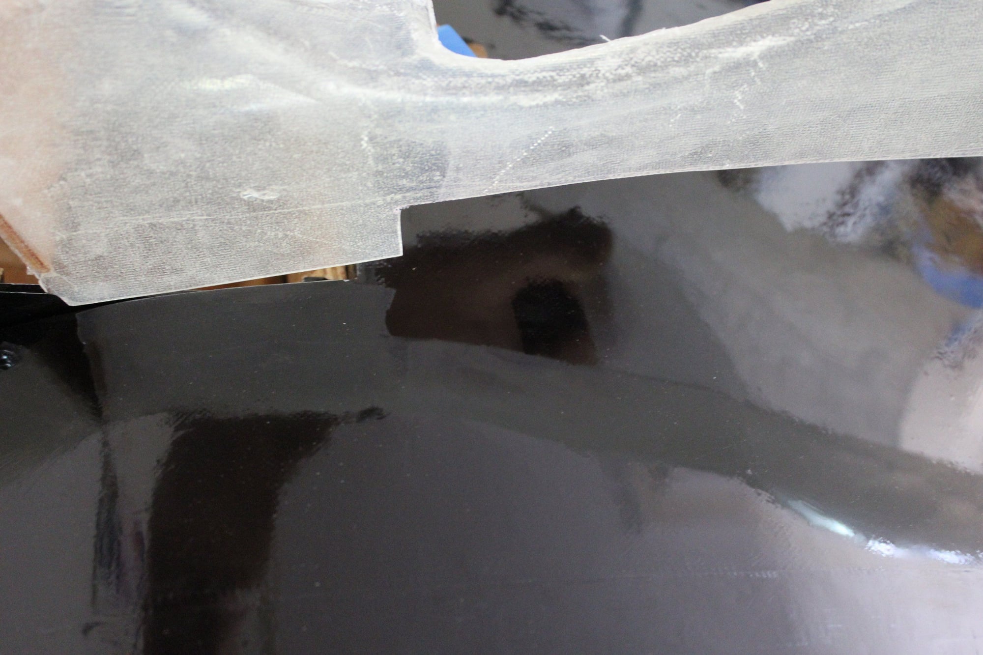
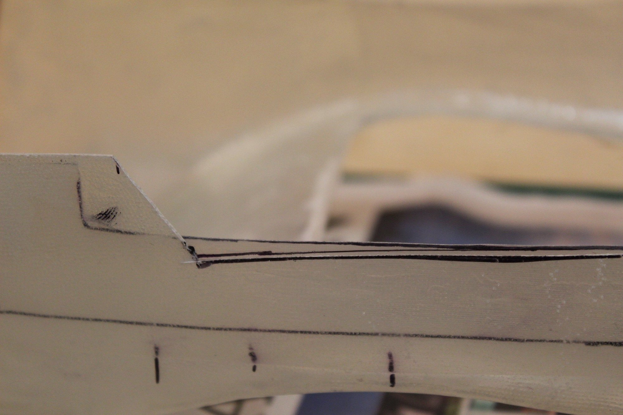
Fitting the wing cover over the wing was much more challenging than expected. It took a fair amount of time to trim it to shape, finding out I messed up and cut incorrectly, and fixing my mistake...

Cheers,
Eran
Cheers,
Eran